Introduction to ICL7107
Intersil ICL7107 is an analog to digital converter that has a built-in 3 1/2 display decoder/driver. It can measure up to 200V DC input. The DC input voltage has polarity so we don’t worry about damage of IC.
The input measuring signal is analog voltage. It does not mean that we can only use it to measure dc voltage. We can use another analog sensor such as analog type temperature sensor (LM35) to measure temperature or analog type current sensor to measure electrical current.
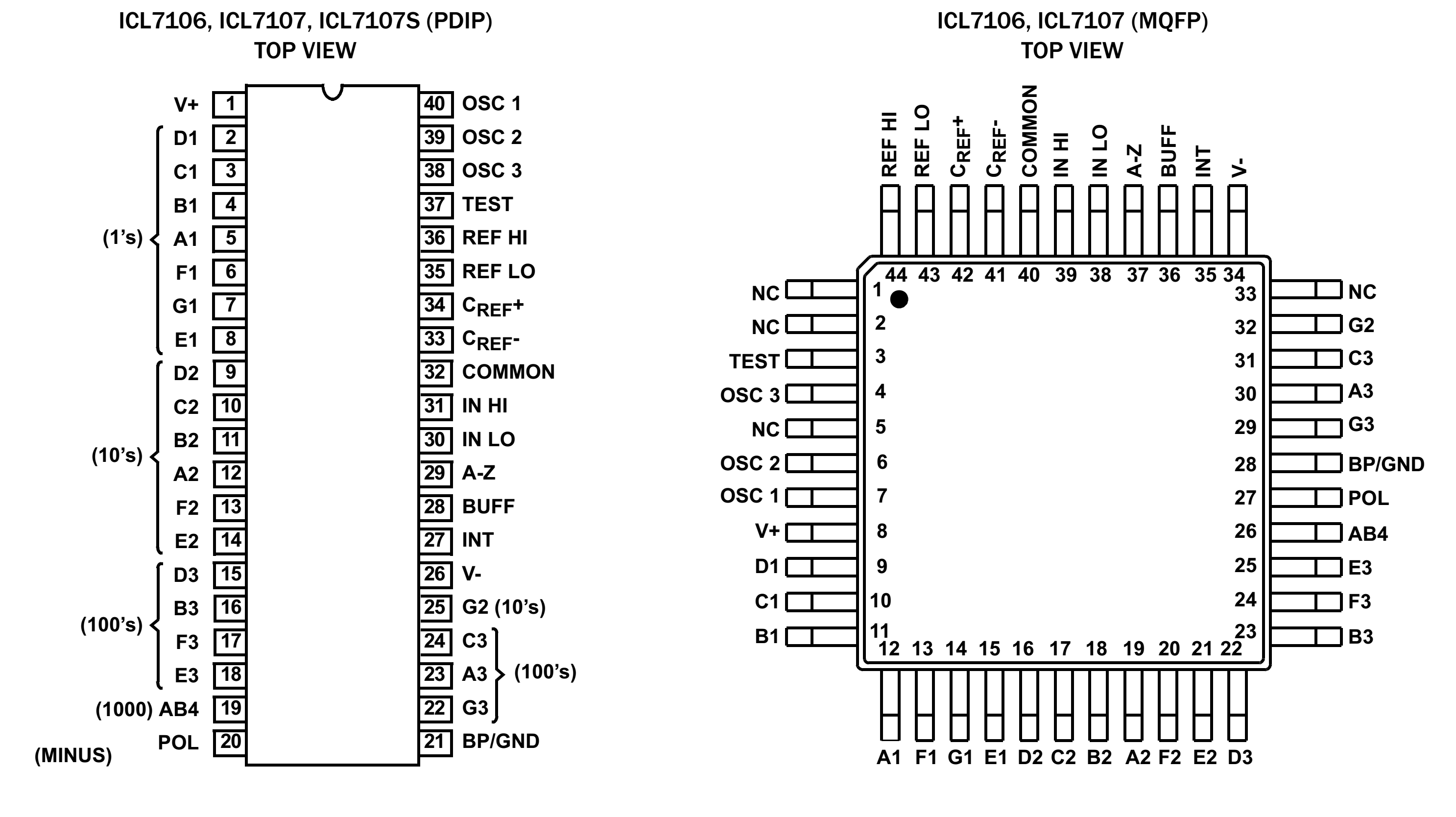
The diagram below shows the pin configuration of ICL7107 with two types of packages.
Circuit design
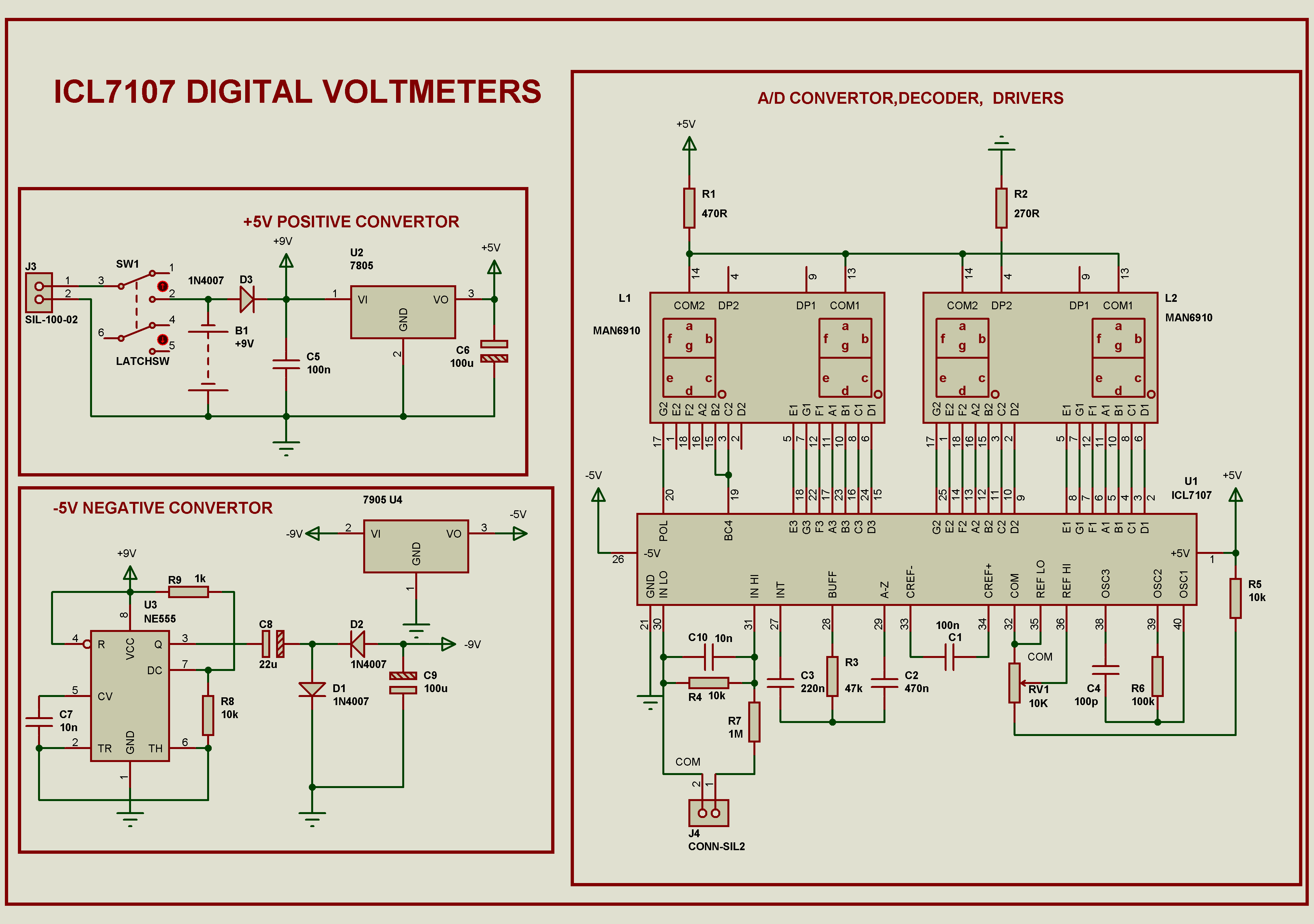
I create the package for this IC by myself. In the simulation software there’s only the symbol that I create but there’s no simulation capability. This module is designed to measure a DC voltage up to 200V with polarity. The schematic below show the full design of this project.
Power supply section
As mention in the previous section this IC could operate in two modes. I choose split mode that’s -5V to +5V supply. So we need some power converter block to get this mode.
This Module is powered by a +9V battery. From the +9V source there’s a block DC/DC regulator giving a +5V regulated supply voltage.
From the +5V regulated block we convey it to another block that function as a positive to negative converter. I convert from +5V to -5V. However the circuit is more complex and we will not cover its operation here.
Display section
This IC contains a seven segments display (SSD) driver/decoder. It can drive the SSD directly without any resistors. The SSD are individual digit and common anode type. In this project I use 0.56 inch size. I added some resistors to each common of digit to decrease the current flow through thus decreasing the brightness of all segments. There’s are four digits in which the first is to display polarity and the number ‘1’ while the remaining 3 digits is use to display voltage value with one floating point at the last digit.
Reference capacitor
This capacitor(C1) help the system from rollover error. A 0.1uF value gives a good result of performance.
Integrating resistor
Integrating resistor(R3) is used for buffer amplifier and integrator. In this case the output scale is 200mV so we select 47kΩ value.
Integrating capacitor
The integrating capacitor(CINT) relates to the voltage swing. We must select it carefully. If the module is design to read analog value three times per second the value of CINT must be 0.22uF or 0.10uF.
Auto-Zero capacitor
Auto zero capacitor (C-AZ) effect the noise of the system. When we use 200mV scale the C-AZ must be 0.47uF. In the case of 2V scale it must be 0.047uF.
Oscillator components
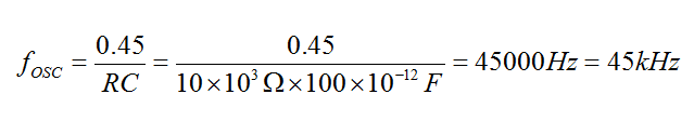
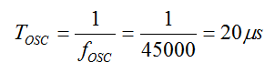
Resistor(R6) and capacitor (C4) is the component of RC Oscillator. In this case we use R=100kΩ and C=100uF. It will generate the oscillator of frequency:
The period is :
The conversion cycle is:
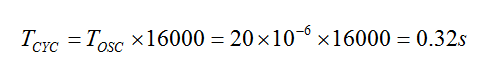
Since the conversion takes 320ms. So it generate the output of analog input voltage 3 times per second.
Voltage reference and display count
The voltage reference is use for reference voltage for ADC. There are two pins REF HI and REF LOW. REF HI is the positive voltage reference while REF LO is the negative voltage reference. In this case I wire REF LO to analog common (COM).
Reference voltage effect the output. if we don’t set them properly the display voltage could be wrong. So adjust the reference voltage(VREF) by a POT RV1 connect in series with R5. We must set VREF to 1V by adjusting the POT.
The input voltage is the signal to be measure by the module. It has polarity: negative and positive determined by IN HI (+) and IN LO (-). As usual it can measure 2V maximum.
We use voltage divider to scale the measuring voltage down. In this case we scale it to 1:100.
We have the relation of this circuit below.
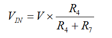
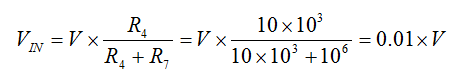
In our module R4=10kΩ and R7=10MΩ. Thus
The displayed voltage count is determined by:
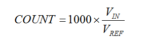
We set VREF to 1V by adjusting the POT.
For example we measure a battery of voltage V=12.2V. From our equation Vin = 0.01 x V = 0.01 x 12.2 = 0.122V.
Thus the display count is:
COUNT = 1000 x 0.122V / (1V) = 122
To get 12.2V we must place the floating point before the last most-right digit. I saw a lot of microcontroller versions of this meter.
Completed module and Gallery
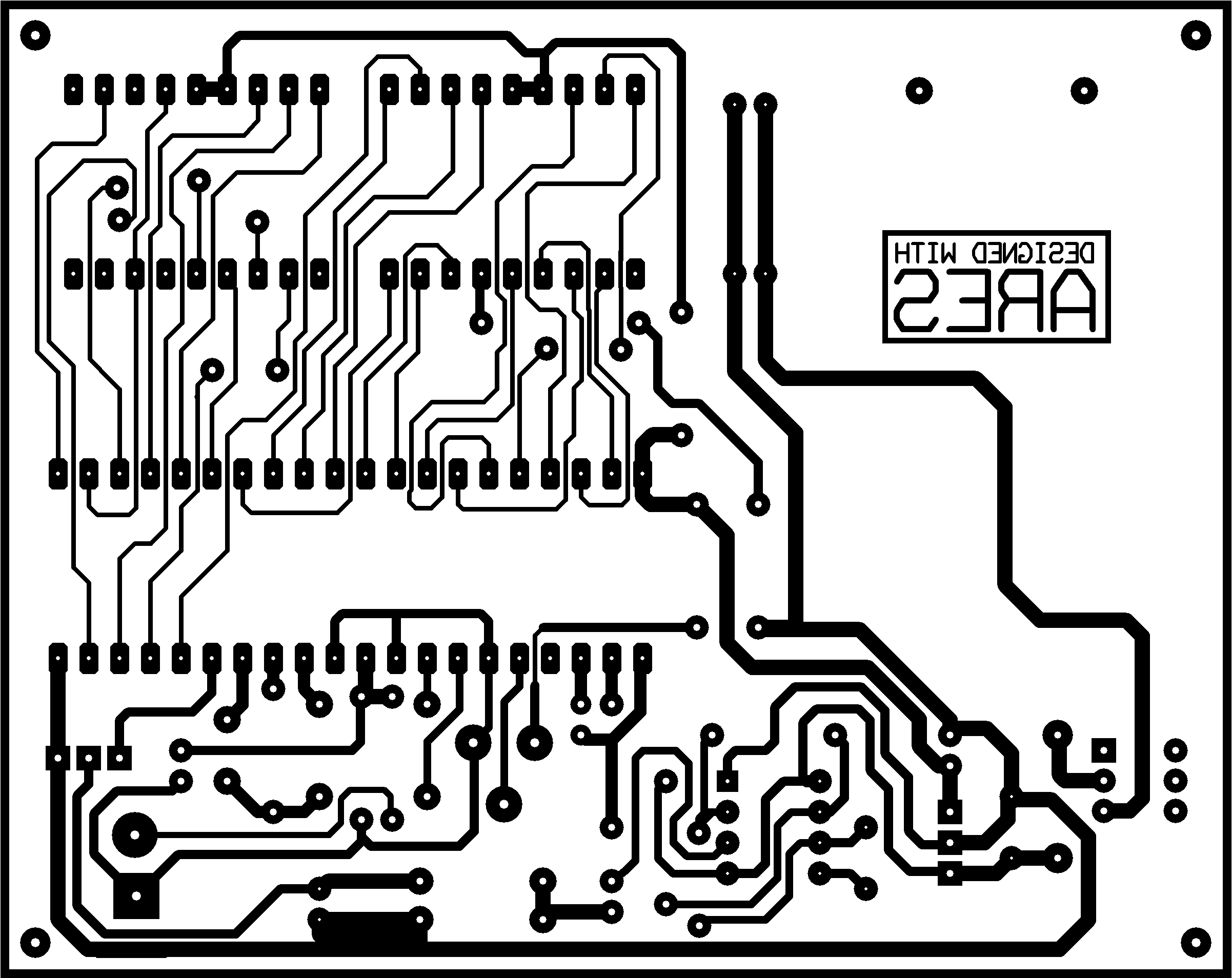
I attached the design file here. The PCB artwork is shown below:
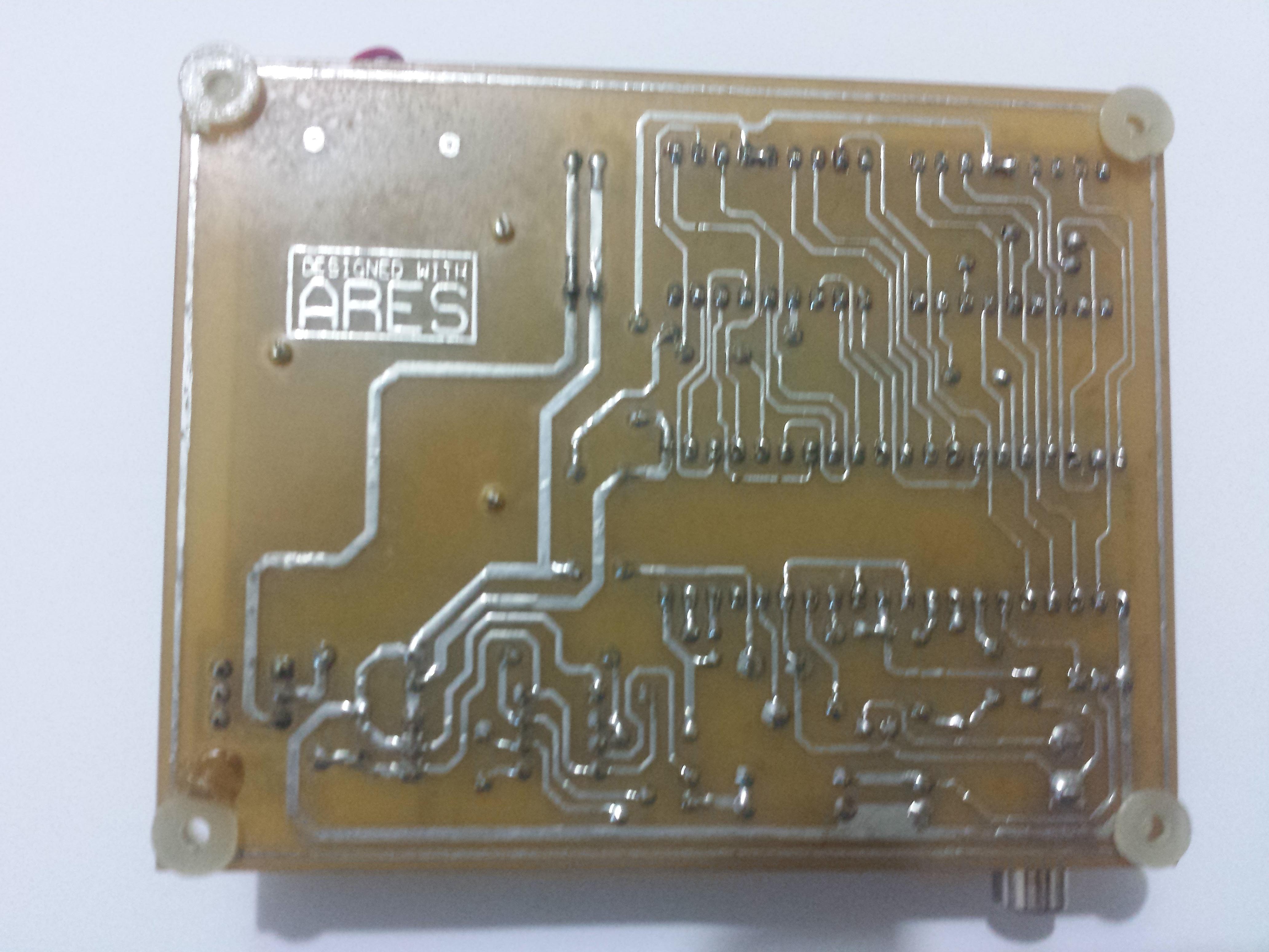
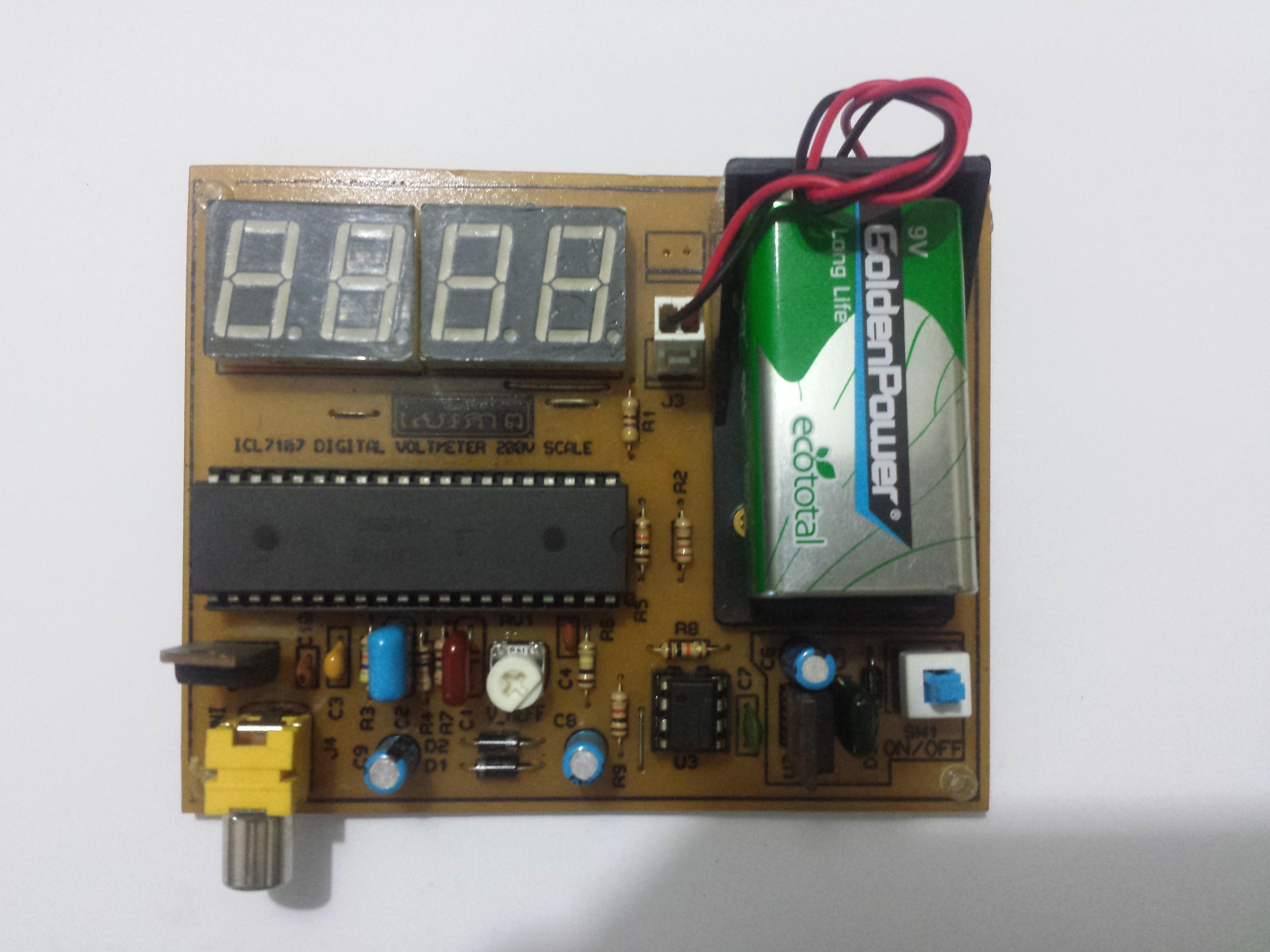
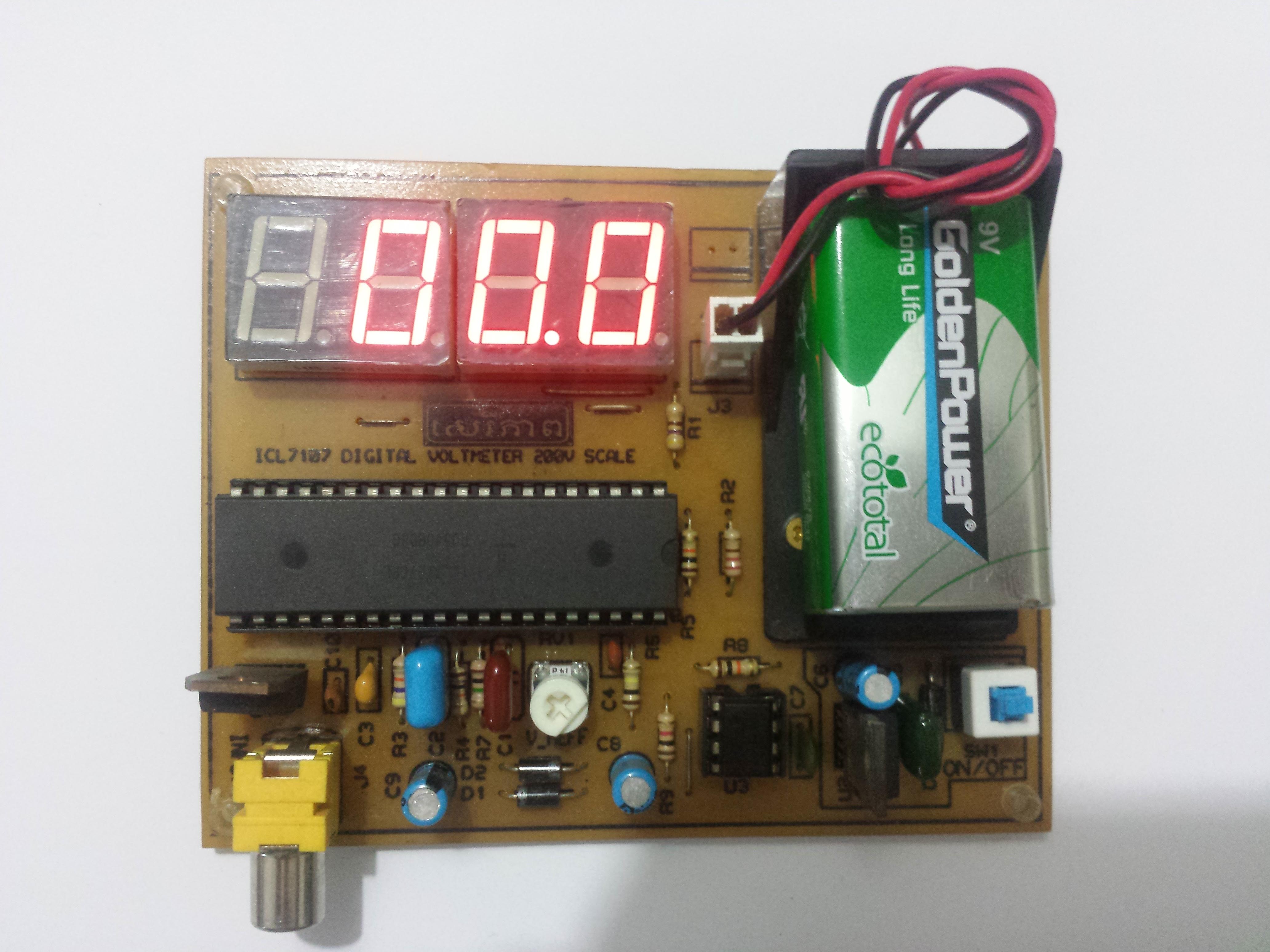
Here’s the picture of finished work.
Here’s the video that I tested this module.
For a better PCB quality, we can make an order from PCB fabrication service at affordable price.

Bill of Material
Bill Of Materials
=================
Design Title:    LAB
Document Number:
Revision:
Author:
Created:         Sunday, March 6, 2022
Modified:        Sunday, March 6, 2022

QTY  PART-REFS                     VALUE           CODE            COST
---  ---------                     -----           ----            ----
Modules
-------

Capacitors
----------
2    C1,C5                         100n            Maplin YR75S
1    C2                            470n            Maplin RG25C
1    C3                            220n            Maplin RG24B
1    C4                            100p            Maplin WX56L
2    C6,C9                         100u            Maplin KQ70M
1    C7                            10n             Maplin WX77J
1    C8                            22u             Maplin KQ65V
1    C10                           10n             Maplin YR75S

Resistors
---------
1    R1                            470R            M470R
1    R2                            270R            M270R
1    R3                            47k             M47K
3    R4-R5,R8                      10k             M10K
1    R6                            100k            M100K
1    R7                            1M              M1M
1    R9                            1k              M1k

Integrated Circuits
-------------------
1    U1                            ICL7107
1    U2                            7805
1    U3                            NE555
1    U4                            7905

Transistors
-----------

Diodes
------
3    D1-D3                         1N4007

Miscellaneous
-------------
1    B1                            +9V
1    J3                            SIL-100-02
1    J4                            CONN-SIL2
2    L1-L2                         MAN6910
1    RV1                           10K             Digikey 3005P-10
1    SW1                           LATCHSW

One thought on “Building a digital voltmeter using ICL7107”