UV timer create a accurate time for the PCB expose box. Without buying a ready to use timer, we can make it by a simple programming on an 8-bit embedded controller.
The picture of the completed project
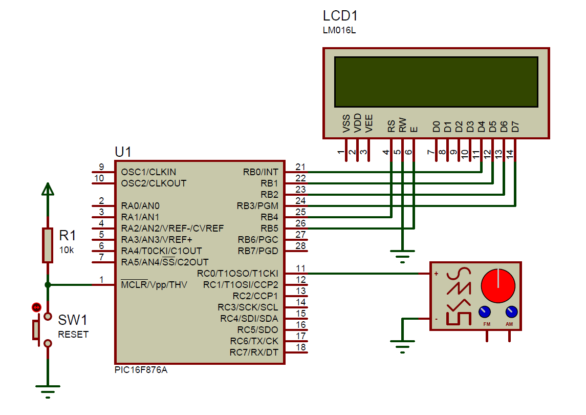
I make this stuff using PIC16F876A. For the project details, click here.
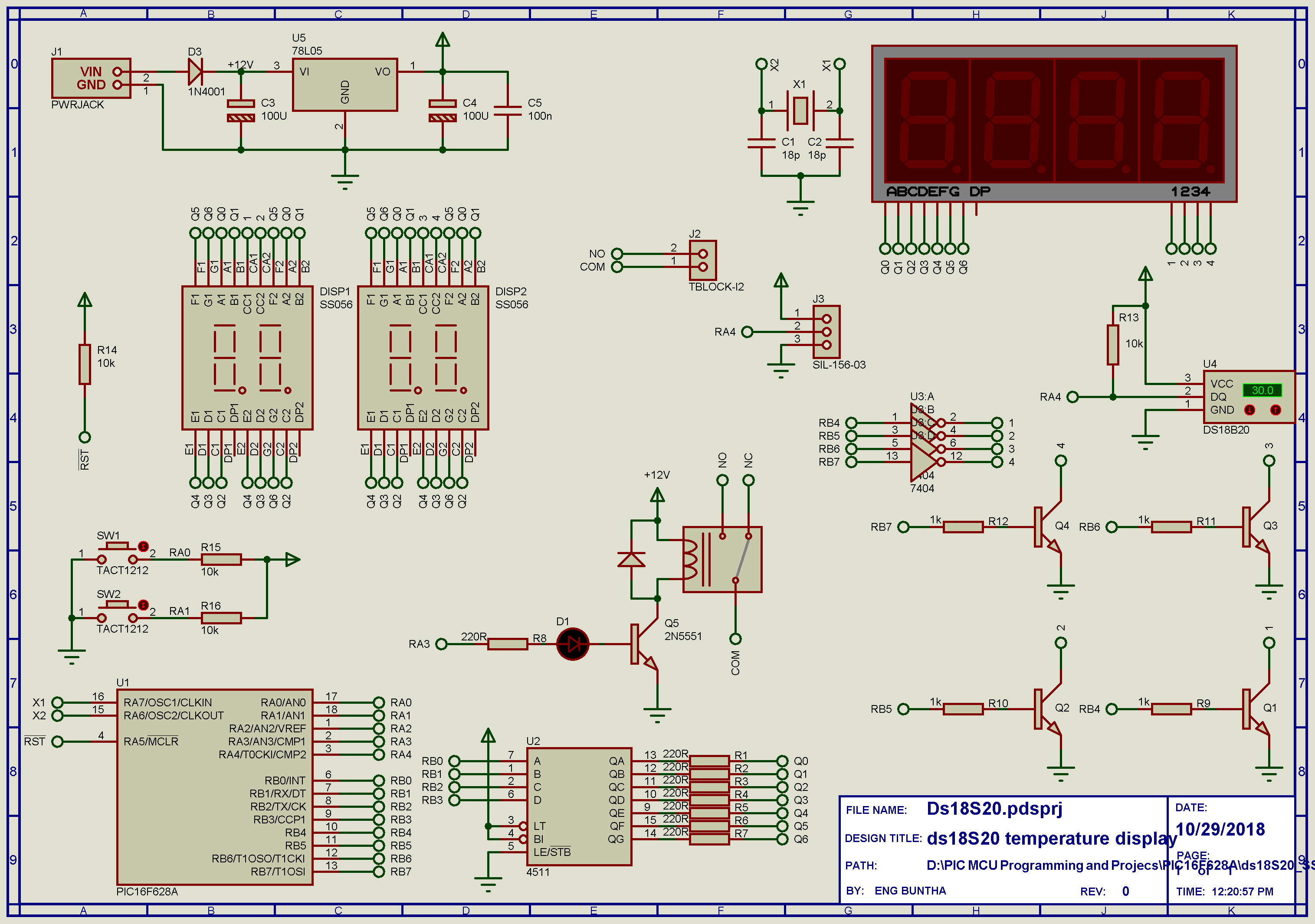
A series of ds18S20 and ds18B20 of digital temperature sensor uses 1-wire bi-directional protocol to request and receive temperature data. DS18S20 has 9-bit resolution while ds18B20 has 12-bit resolution.
In this project I create a system that follow these operations:
The CPU reads temperature data and display it on a MUX SSD.
A two-switch input uses to set the temperature for turning relay on/off.
Each time I set the temperature, the CPU save that setting to the EEPROM
Anytime the current temperature exceeds the setting, the relay works.
The design is controlled by a PIC16F628A/PIC16F84A CPU. The inputs are: ds18X20 and input tactile switches. The outputs are a SPDT relay and a four-digit MUX SSD that I posses. I use an extra 4511 BCD to SSD decoder that I left. The system is powered by a +12V maximum AC/DC input to a regulated +5V/100mA 78L05 voltage stabilizer.
The firmware is written using MikroC pro for 8-bit PIC. The schematic capture and simulation is made using Proteus VSM 8.
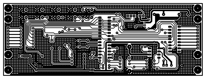
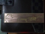
I made my own PCB with in-house components. For more high quality PCB, choosing a PCB supply service could be a good option.
Schematic: 7404 is use for simulation only and 2N5551 is use for PCB design only
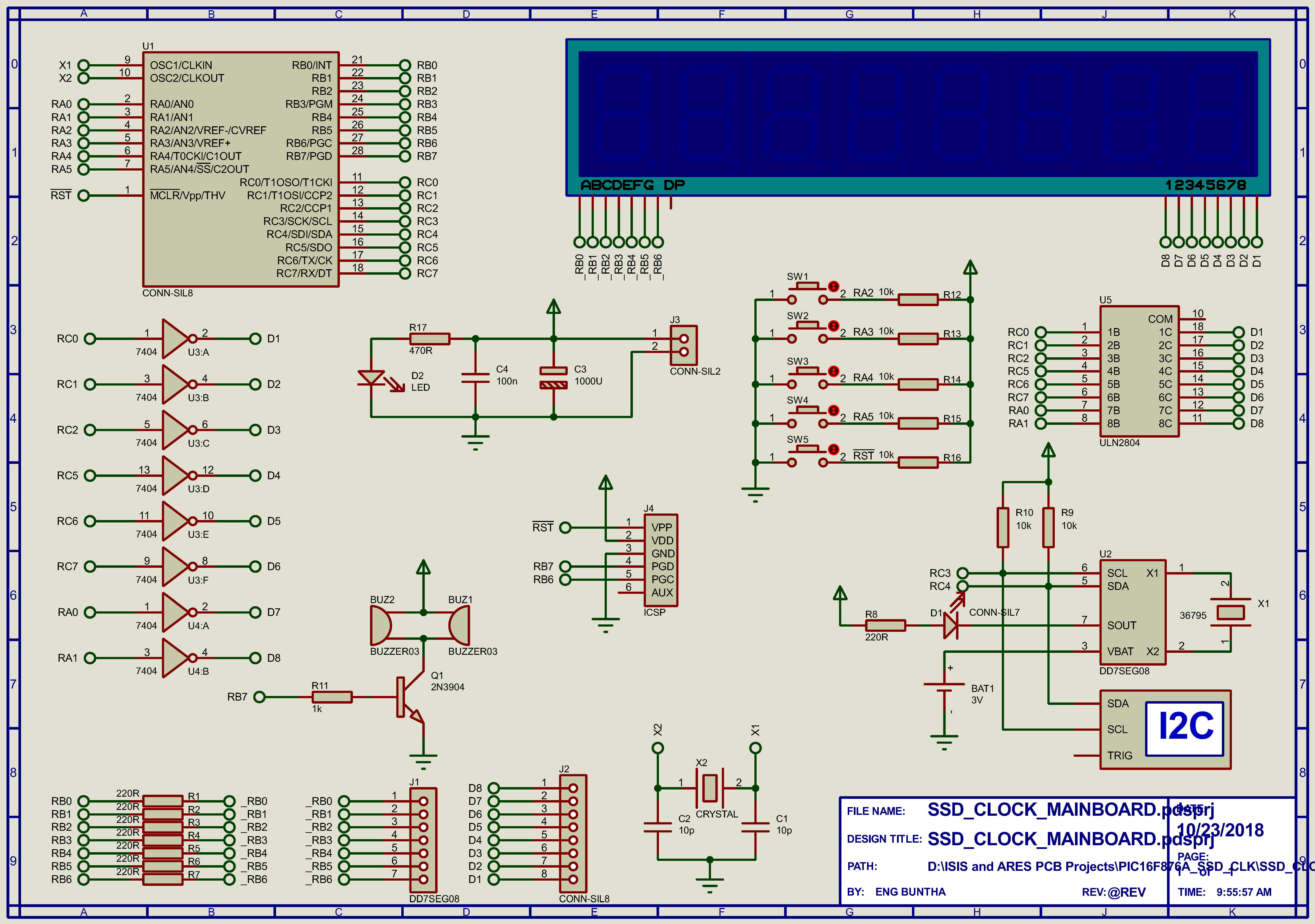
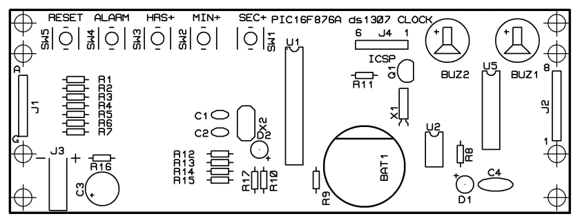
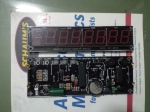
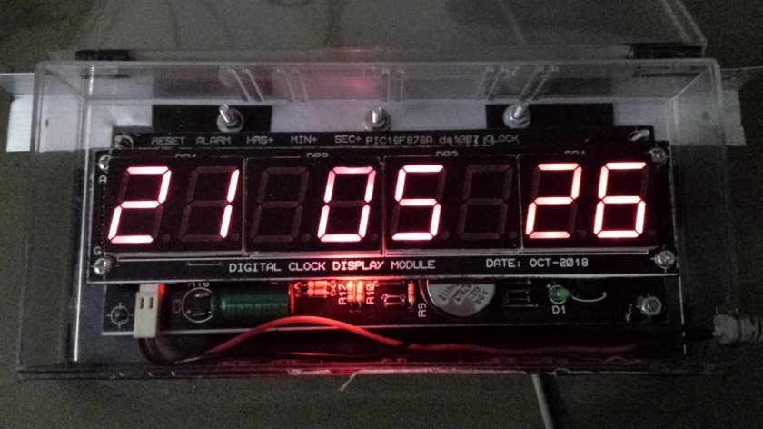
I made a seven segments clock display with ds1307 RTC. It feature an 8-digit hh-mm-ss with adjustment and alarm setting. Due to a design and PCB fabrication difficulties, I decided to divide two distinct board, one’s for the main controller board and another one is a display board that stack on the main controller board. The schematic below is the main controller board powered by PIC16F876A.
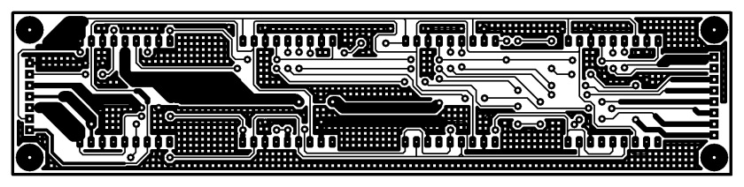
Schematic Circuit 7404 is just use for simulation only not for PCB design. ULN2804 is not include in simulation but for PCB design. copper soldering side component side
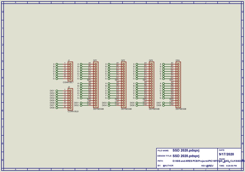
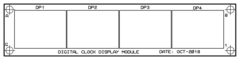
A 7-segments display board stack above the main board.
Schematic of multiplexed seven segments display board 7-segment display board copper side components legend side
I have assembled and test this project with error-free.
Making the PCB for this project by hands could spend a lot times etching, drilling and soldering. The user could select a PCB service from a PCB supplier.
PIC16F876A is an 8-bit PIC microcontroller with 28-pin package. its package is also come with a DIP version suitable for hobbyist projects and experiment.
This device is fairly fit to this project referring to the numbers of I/O pins requirement, RAM and ROM space.
An I2C peripheral is also require because it needs to read/write timing data between the DS1307 real time clock chip.
The CPU uses its timer0 timer ticks to multiplex an 8-digits 7-segments display. The display made from eight individual 0.8 inch hi-read common cathode display.
I put some buttons to adjust the HH:MM:SS and also the alarm setting. An output active buzzer beeps any time the alarm time is reached. Buttons and buzzer active time is implemented using the timer0 timer ticks method.
MPLABX XC8 is a compiler of choice for this project. Using this free compiler, the coder can access all the registers definition of the SFR just like one’s the the assembly language programming.
Source code and completed PCB project could be get from GitHub.
Digital Volt Meter (DVM) could be built from scratch using any ADC IC such as ICL7107 or ICL7135. However those IC have a large pin counts requiring us more time to wire.
Using a microcontroller we can reduce the number of pin count for the display. A common way is using multiplexed display.
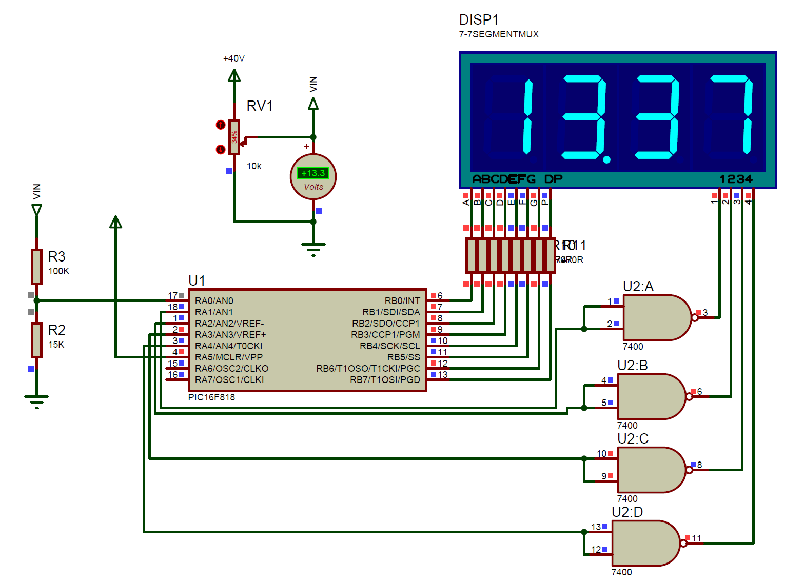
In this project I use PIC16F818 with a 10-bit built-in ADC to read analog voltage range from 0 to +40V DC.
ADC work only with +5V. So I use the voltage divider rule to reduce the scale of input voltage. As show in the schematic below, the resistors R3 and R2 are use for voltage divider. From voltage divider rule I get the scale factor of 0.13.
Frequency meter can be made using a simple method, but this method could measure a low frequency range. It’s suitable for any application at the system that process with a low frequency input.
I use a C-loop to measure the input frequency. The loop repeats at 55800 times making a one-second period. during this period if the input state is High that will increase the counter.
The signal is being fed to pin RC0. While PORTB is use for output LCD driving.