Using a prototype board for micro-controller could save circuit construction, reducing any wrong wiring on bread-board. A development board or prototype board for PIC micro-controller costs around 40USD at local electronics stores.

However we can make our own hand-made development board at home using a simple DIY method with some used components. It doesn’t cost any money due to my own in-house components.

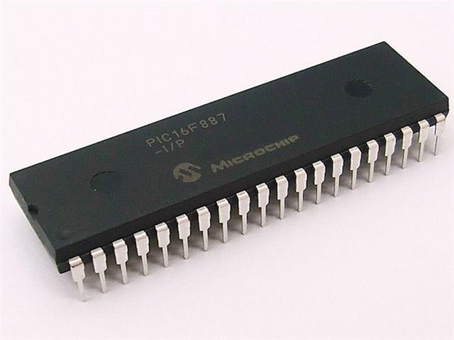
I have some 8-bit micro-controller including PIC1F6877A, PIC16F887, PIC18F4520, PIC18F4450, etc. So Decide to make my own prototype board using existing components.


This DIY prototyping board could fit PIC16F877A, PIC16F887, PIC18F4550, etc. It has a USB type-B connector for PIC18F4550 USB micro-controller. For more information you can see this link.
It has some sample code written using MPLABX IDE and XC8 C compiler,
LCD and Sensors
- PIC16F887 HD44780 4-Bit LCD Example Using XC8
- PIC16F887 LM35 and LCD Interfacing Example Using XC8
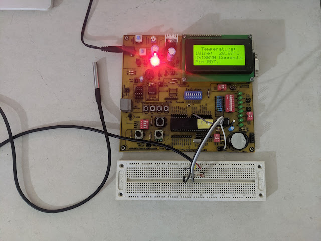
- PIC16F887 DS18B20 LCD Example Using XC8
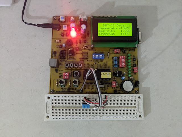
- PIC16F887 DHT-11 LCD Example Using XC8
- PIC16F887 HC-SR04 Distance Sensor LCD Using XC8
Inter Integrated Circuit (I2C)
- PIC16F887 I2C DS1307 RTC LCD Using XC8
- PIC16F887 I2C AT24C16B EEPROM LCD Using XC8
- PIC16F887 SH1106 I2C OLED Display Example using XC8
- PIC16F887 TM1637 Six Digits 7-Segment Display Example Using XC8
- PIC16F887 TM1637 Display and Key Scan Example using XC8
- DIY PIC16F887 Micro-controller Prototype Board
- PIC16F887 PCF8574 I2C Example using XC8
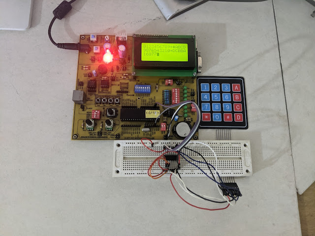
- PIC16F887 KeyPad and Character LCD Example using XC8
- PIC16F887 PCF8574AP I2C 4×4 KeyPad using XC8
- PIC16F887 PCF8574AP I2C LCD Example using XC8
- PIC16F887 MCP23017 I2C GPIO Example using XC8
- PIC16F887 MCP23017 Key Pad and 7-Segment Display Example using XC8
- PIC16F887 MCP23017 I2C LCD Example using XC8
- PIC16F887 MCP23017 LCD and Keypad Interfacing using XC8
Serial Peripheral Interface (SPI)
- PIC16F887 SPI MCP23S17 Character LCD and KeyPad XC8 Example
- PIC16F887 SPI SN74HC165 LCD XC8 Example
- PIC16F887 SPI 25AA010A EEPROM XC8 Example
- PIC16F887 SPI 93C46B EEPROM XC8 Example
- PIC16F887 SPI and Nokia 5110 LCD XC8 Example
- PIC16F887 Serial Peripheral Interface Example
- PIC16F887 SPI and MCP23S17 XC8 Example
- PIC16F887 SPI MCP23S17 and Character LCD XC8 Example
- PIC16F887 SPI SN74HC165 LCD XC8 Example
- PIC16F887 SPI 25AA010A EEPROM XC8 Example
- PIC16F887 SPI 93C46B EEPROM XC8 Example
- PIC16F887 SPI and Nokia 5110 LCD XC8 Example