A series of ds18S20 and ds18B20 of digital temperature sensor uses 1-wire bi-directional protocol to request and receive temperature data. DS18S20 has 9-bit resolution while ds18B20 has 12-bit resolution.
In this project I create a system that follow these operations:
- The CPU reads temperature data and display it on a MUX SSD.
- A two-switch input uses to set the temperature for turning relay on/off.
- Each time I set the temperature, the CPU save that setting to the EEPROM
- Anytime the current temperature exceeds the setting, the relay works.
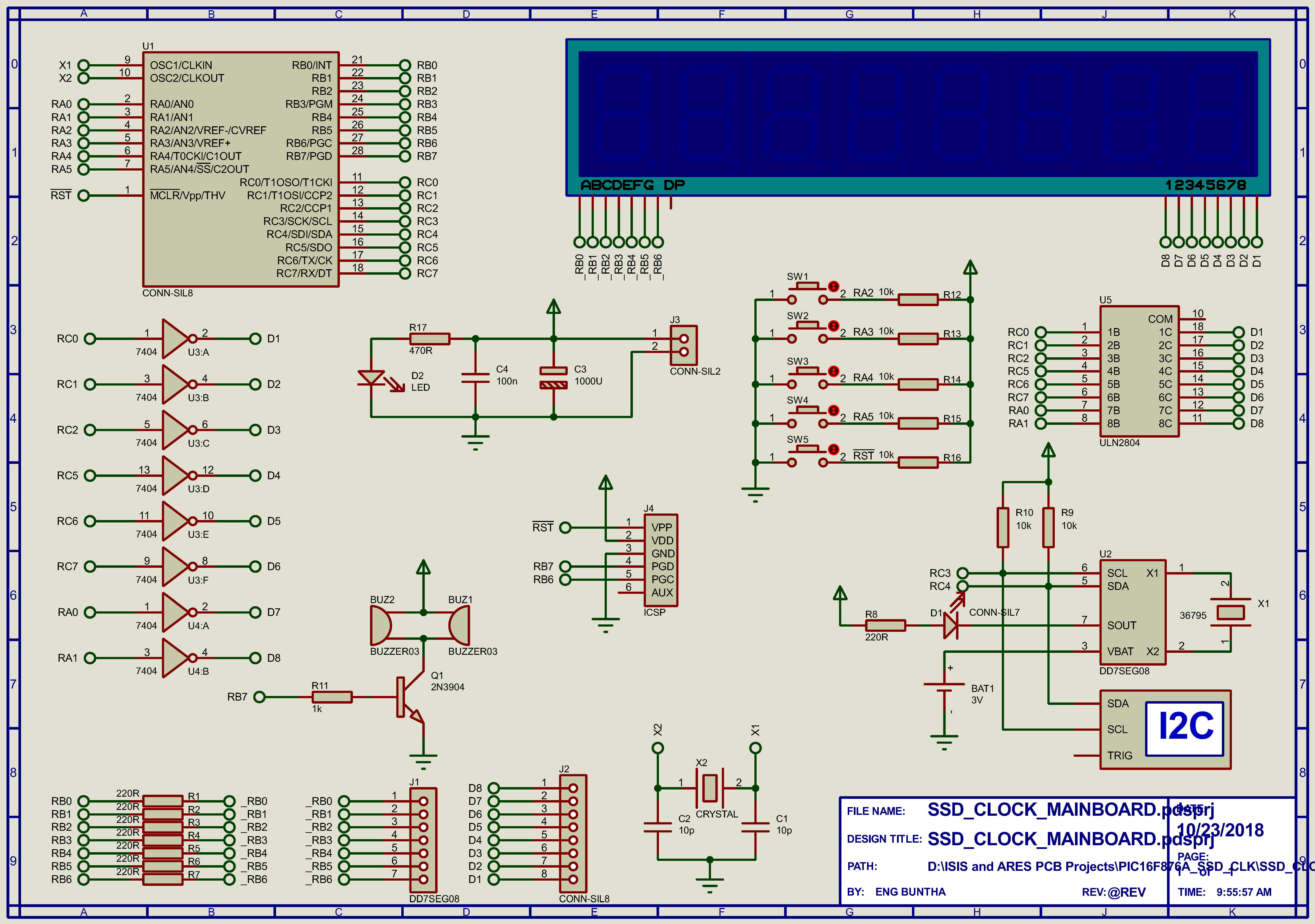
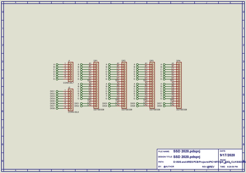
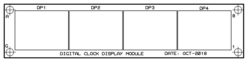
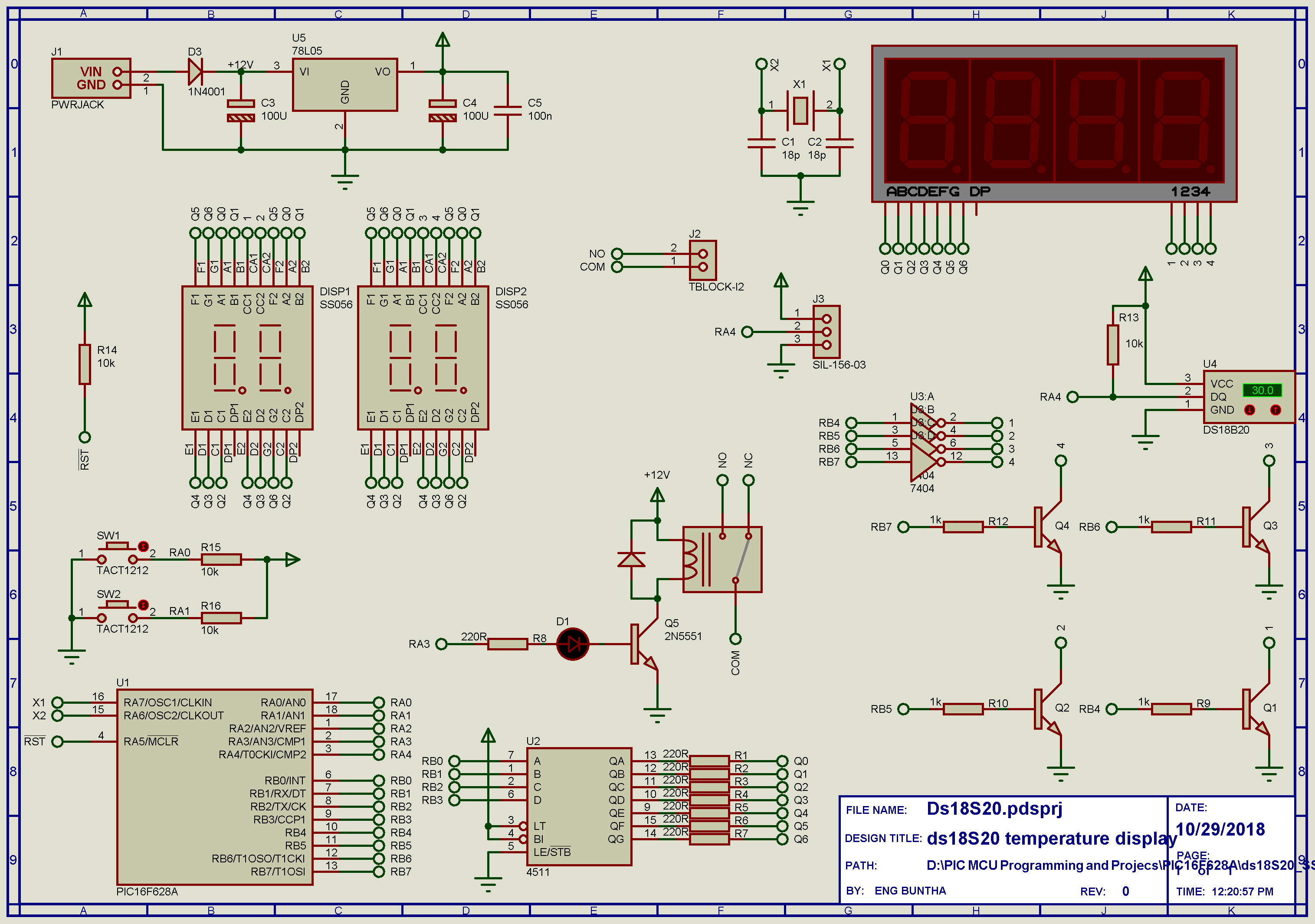
The design is controlled by a PIC16F628A/PIC16F84A CPU. The inputs are: ds18X20 and input tactile switches. The outputs are a SPDT relay and a four-digit MUX SSD that I posses. I use an extra 4511 BCD to SSD decoder that I left. The system is powered by a +12V maximum AC/DC input to a regulated +5V/100mA 78L05 voltage stabilizer.
The firmware is written using MikroC pro for 8-bit PIC. The schematic capture and simulation is made using Proteus VSM 8.
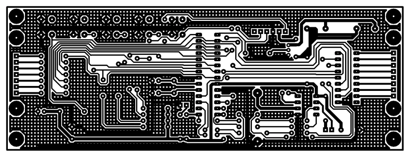
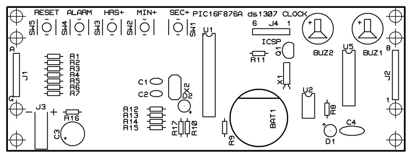
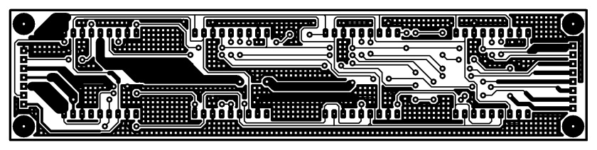
I made my own PCB with in-house components. For more high quality PCB, choosing a PCB supply service could be a good option.
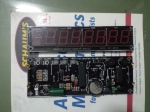
Project galleries:


Project archive:
https://github.com/BongPeav/MikroC-8-bit-PIC/raw/master/ds18S20_SSD_CON.rar
MikroC source code for this project:
#define INC     PORTA.RA0
#define DEC     PORTA.RA1
#define RLY     PORTA.RA3

unsigned char T0Cnt,setTemp,setRead;
//  Set TEMP_RESOLUTION to the corresponding resolution of used DS18x20 sensor:
//  18S20: 9  (default setting; can be 9,10,11,or 12)
//  18B20: 12
const unsigned short TEMP_RESOLUTION = 12;
unsigned Cnt1,Cnt2,Cnt3,Cnt4;
bit minus,ssdOn;

void interrupt(void){
     asm{
         CLRWDT
         }

     if(INTCON.T0IF==1){
       T0Cnt++;
       INTCON.T0IF=0;
       }
}

void ioInit(void);
void ssdOut(unsigned int temp);
void tempRead(void);
unsigned int gettemp();
void tempSet(void);
void dataRead(void);

void main() {
     unsigned tempData,oldData;
     ioInit();
     dataRead();
     tempData=getTemp();
     tempData=0;
     delay_ms(20);
     oldData=0;
     while(1){
              if(ssdOn==1){
              if(Cnt1>=75){
                 tempData=getTemp();
                 tempData=getTemp();

                 Cnt1=0;
                 }

       ssdOut(tempData);
       }
       else
       ssdOut(setTemp);
       tempSet();
       if(Cnt4>=50){
       if(tempData>=setTemp)  {
                           RLY=1;
                           Cnt4=0;
                           }
       else                {
                           RLY=0;
                           Cnt4=0;
                           }

                           }
       }
}

void ssdOut(unsigned int temp){
     char ssd[10]={0xC0,0xF9,0xA4,0xB0,0x99,0x92,0x82,0xF8,0x80,0x90};
     char d1,d2,d3;
     d1=temp/100;
     d2=(temp%100)/10;
     d3=temp%10;

     switch(T0Cnt){

                   case 2 :
                        PORTB=0x00;
                        PORTB=d1&0x0F;
                        PORTB|=0x20;
                        break;

                   case 3 :
                        PORTB=0x00;
                        PORTB=d2&0x0F;
                        PORTB|=0x40;
                        break;

                   case 4 :
                        PORTB=0x00;
                        PORTB=d3&0x0F;
                        PORTB|=0x80;
                        break;

                   case 5 :
                        Cnt1++;
                        Cnt2++;
                        CNt3++;
                        Cnt4++;
                        T0Cnt=0;
                        break;
                   }
}

void ioInit(void){
     PCON.OSCF=1;
     TRISB=0x00;
    TRISA=0x03;
    CMCON=0x07;
     PORTA=0x00;
     OPTION_REG=0x03; // 1:16
     INTCON.GIE=1;
     INTCON.T0IE=1;
     INTCON.T0IF=0;
     PORTB=0x00;
     T0Cnt=0;
     Cnt1=0;
     Cnt2=0;
     Cnt3=0;
     Cnt4=0;
     minus=0;
     ssdOn=1;
}

unsigned int gettemp(){
       unsigned int temp;
       const unsigned short RES_SHIFT = TEMP_RESOLUTION - 8;

       Ow_Reset(&PORTA, 4);                         // Onewire reset signal
       Ow_Write(&PORTA, 4, 0xCC);                   // Issue command SKIP_ROM
       Ow_Write(&PORTA, 4, 0x44);                   // Issue command CONVERT_T
       Delay_us(120);

       Ow_Reset(&PORTA, 4);
       Ow_Write(&PORTA, 4, 0xCC);                   // Issue command SKIP_ROM
       Ow_Write(&PORTA, 4, 0xBE);                   // Issue command READ_SCRATCHPAD

       temp =  Ow_Read(&PORTA, 4);
       temp = (Ow_Read(&PORTA, 4) << 8) + temp;
       if(temp&0x8000){
                             minus=1;
                             temp=~temp;
                             }
       else
           minus=0;

       temp = temp >> RES_SHIFT ;
       return temp;
}

void tempSet(void){
     if(DEC==0&&Cnt2>=10){
                ssdOn=0;
                if(setTemp<120) setTemp++;
                EEPROM_Write(0x00,setTemp);
                Cnt3=0;
                Cnt2=0;
                }

     if(INC==0&&Cnt2>=10){
     ssdOn=0;
                if(setTemp<120) setTemp--;
                EEPROM_Write(0x00,setTemp);
                Cnt3=0;
                Cnt2=0;
                }
     setRead=setTemp;
     if(Cnt3>=150) {
       ssdOn=1;
       Cnt3=0;
     }

}

void dataRead(void){
     setTemp=EEPROM_Read(0x00);
}
For any custom design relates to this project, you can contact the author.