
Introduction
In most of PIC Microcontroller the MCLR (Master Clear Reset) is use for reset only. But in PIC16F887 this pin could be use either a digital input pin or reset pin. So the the microcontroller doesn’t have master clear reset. The other reset could be power up timer or WDT reset.
Programming
If we use MCRL as digital input this pin could be RE3. To set it to digital input we must set the direction to input by setting corresponding TRIS register. So we set TRISE3 of TRISE to 1.
To get started with MikroC for PIC16F887 click here.
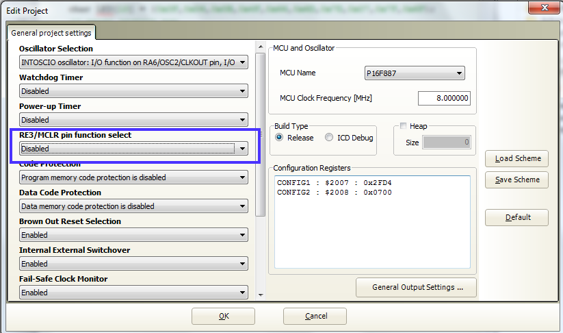
In the configuration bit we disable the Master Clear Reset by using Project Setting as shown below.
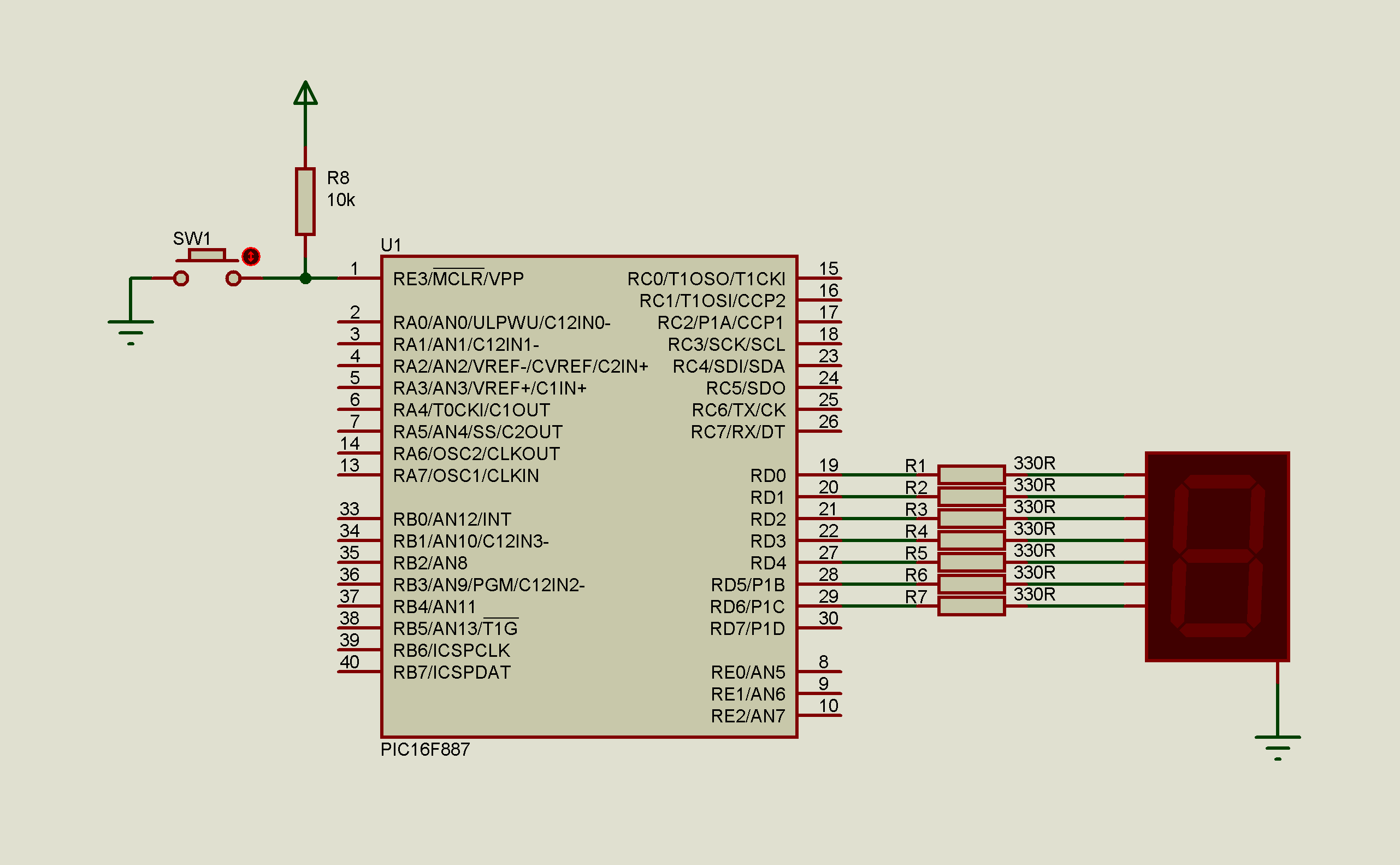
Here’s the schematic.
Attached is the full package of this example.
In the code editor window of MikroC write the code below.
/* Using RE3/MCLR pin of PIC16F887 as an input
we don't use MCLR as Reset So it can run
without MCLR reset.
Author: ENG BUNTHA */

#define TACT PORTE.RE3     // use RE3 as digital input

void main() {
     char LED[10] = {0x3F,0x06,0x5B,0x4F,0x66,0x6D,0x7D,0x07,0x7F,0x6F};
     // seven segment map
     char i=0;

     // i/o port initialization
     PORTD=0x00;
     TRISD=0x00;               // SET PORTD AS DIGITAL OUTPUT
     PORTE=0x00;
     TRISE.TRISE3=1;           // SET RE3 AS AN INPUT

     // OSCILATOR CONFIGURATION
     OSCCON.IRCF0=1;
     OSCCON.IRCF1=1;
     OSCCON.IRCF2=1;           // IRCF=0b111 is SET TO 8MHz

     while(1) {
              if(TACT==0) {
                          while(TACT==0);    // WAIT UNTIL SWITCH IS RELEASE
                          i++;
                          if(i==10)          i=0;
                          }
              PORTD=LED[i];
              }
}
