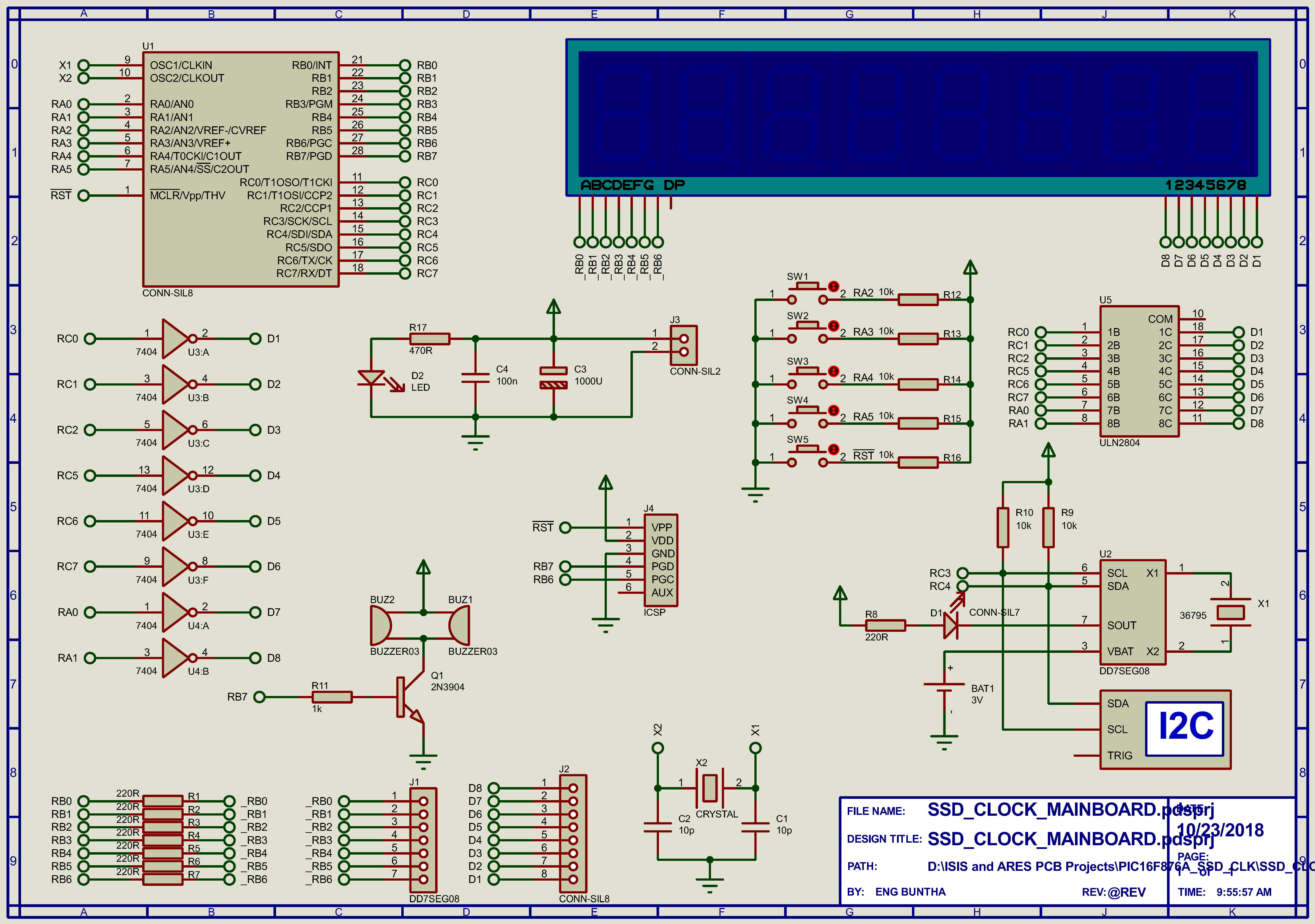
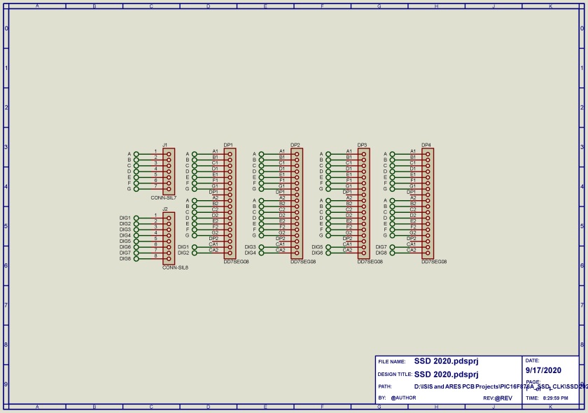
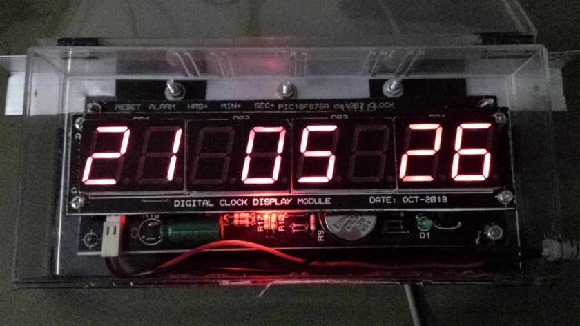
I made a seven segments clock display with ds1307 RTC. It feature an 8-digit hh-mm-ss with adjustment and alarm setting. Due to a design and PCB fabrication difficulties, I decided to divide two distinct board, one’s for the main controller board and another one is a display board that stack on the main controller board. The schematic below is the main controller board powered by PIC16F876A.
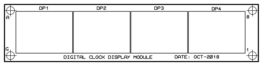
A 7-segments display board stack above the main board.
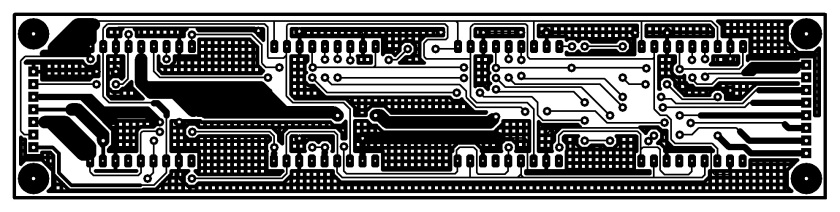


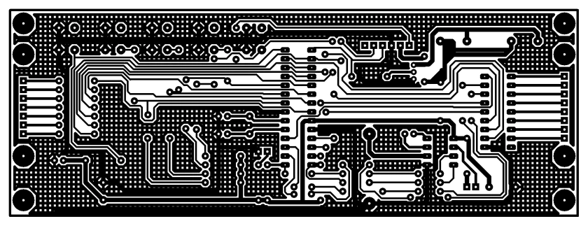
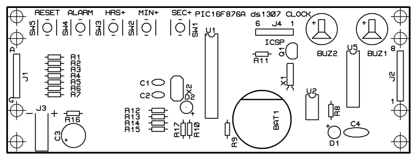
Making the PCB for this project by hands could spend a lot times etching, drilling and soldering. The user could select a PCB service from a PCB supplier.
PIC16F876A is an 8-bit PIC microcontroller with 28-pin package. its package is also come with a DIP version suitable for hobbyist projects and experiment.
This device is fairly fit to this project referring to the numbers of I/O pins requirement, RAM and ROM space.
An I2C peripheral is also require because it needs to read/write timing data between the DS1307 real time clock chip.
The CPU uses its timer0 timer ticks to multiplex an 8-digits 7-segments display. The display made from eight individual 0.8 inch hi-read common cathode display.
I put some buttons to adjust the HH:MM:SS and also the alarm setting. An output active buzzer beeps any time the alarm time is reached. Buttons and buzzer active time is implemented using the timer0 timer ticks method.
MPLABX XC8 is a compiler of choice for this project. Using this free compiler, the coder can access all the registers definition of the SFR just like one’s the the assembly language programming.
Source code and completed PCB project could be get from GitHub.
https://github.com/BongPeav/xc8/raw/master/SSD_CLOCK.X.rar
MPLABX XC8 source code lists below:
#include <xc.h>
#include "config.h"
#include "defination.h"
#include "i2c.h"

unsigned char T0Cnt;
unsigned char T1Cnt;
unsigned char ssdCnt;
unsigned char _time[3];
unsigned char _timeAlarm[3];
unsigned char modeSel;
unsigned char buzTimer;
unsigned char _PORTB;
unsigned int ssdBlink;
bit             blink;
bit             swOn;

void T0Init(void);
void timersTick(void);
void T1Init(void);
void ioInit(void);
void varInit(void);
void clockSetup(void);
void clockAdj(void);
void alarmSet(void);
void alarmCheck(void);
void SSDout(unsigned char hrs,unsigned char mns,unsigned char scs);

unsigned char getDate(unsigned char add);
unsigned char bcd2dec(unsigned char bcd);
unsigned char dec2bcd(unsigned char dec);
void    rtcInit(void);

unsigned char eeRead(unsigned char add);
void eeCommand(void);
void eeWrite(unsigned char add,unsigned char dat);
void alarmLoad(void);

__EEPROM_DATA(12,30,10,0,0,0,0,0);

void interrupt ISR(void){
    if(TMR0IF&&TMR0IE){
        T0Cnt++;
        TMR0=-78;
        TMR0IF=0;
    }

    if(TMR1IF&&TMR1IE){
        T1Cnt++;
        TMR1IF=0;
    }
}

void main(){

    ioInit();
    T0Init();
    i2cMasterInit(100000);
    varInit();
    alarmLoad();
    rtcInit();
    T1Init();
    while(1){
        timersTick();
        SSDout(_time[2],_time[1],_time[0]);
        if(modeSel==0)  clockAdj();
        clockSetup();
        alarmCheck();
    }
}

void T0Init(void){
    T0CS=0;
    PSA=0;
    OPTION_REGbits.PS=0x05; // 1:64
    GIE=1;
    TMR0IE=1;
    TMR0IF=0;
}

void timersTick(void){

    if(T0Cnt>=2){
        ssdCnt++;
        ssdBlink++;
        T0Cnt=0;
    }

    if(ssdBlink>=blinkRate){
        blink^=1;
        if(modeSel==0)
        for(int i=0;i<3;i++){
            _time[i]=getDate(i);
            _time[i]=bcd2dec(_time[i]);
        }
        buzTimer++;
        ssdBlink=0;
    }

    if(T1Cnt>=7){
        swOn^=1;
        T1Cnt=0;
    }
}

void ioInit(void){
    TRISA=0xFC;
    TRISB=0x00;
    TRISC=0x00;
    PORTB=0;
    ADCON1bits.PCFG=0x06;   // all digital
    CMCONbits.CM=0x07;      // comparator off
}

void varInit(void){
    T0Cnt=0;
    ssdCnt=0;
    ssdBlink=0;
    modeSel=0;
    T1Cnt=0;
    buzTimer=0;
}

void SSDout(unsigned char hrs,unsigned char mns,unsigned char scs){
    // COMMON CATHODE
    const unsigned char SEG[10]={0x3F,0x06,0x5B,0x4F,0x66,0x6D,0x7D,0x07,0x7F,0x6F};
    unsigned char hrs10,hrs1,mns10,mns1,scs10,scs1;
/*
    hrs10=hrs>>4;
    hrs1=hrs&0x0F;
    mns10=mns>>4;
    mns1=mns&0x0F;
    scs10=scs>>4;
    scs1=scs&0x0F;
*/

    hrs10=hrs/10;
    hrs1=hrs%10;
    mns10=mns/10;
    mns1=mns%10;
    scs10=scs/10;
    scs1=scs%10;

    switch(ssdCnt){
        case 1 :
            PORTA=0x00;
            PORTC=0x00;
            PORTB=SEG[hrs10]|_PORTB;
            D1=1;
            break;

        case 2 :
            PORTA=0x00;
            PORTC=0x00;
            PORTB=SEG[hrs1]|_PORTB;
            D2=1;
            break;

        case 3 :
            PORTA=0x00;
            PORTC=0x00;
            if(blink){
                PORTB=64|_PORTB;
                D3=1;
            }
            break;

        case 4 :
            PORTA=0x00;
            PORTC=0x00;
            PORTB=SEG[mns10]|_PORTB;
            D4=1;
            break;

        case 5 :
            PORTA=0x00;
            PORTC=0x00;
            PORTB=SEG[mns1]|_PORTB;
            D5=1;
            break;

       case 6 :
            PORTA=0x00;
            PORTC=0x00;
            if(blink){
                PORTB=64|_PORTB;
                D6=1;
            }
            break;

      case 7 :
            PORTA=0x00;
            PORTC=0x00;
            PORTB=SEG[scs10]|_PORTB;
            D7=1;
            break;

      case 8 :
            PORTA=0x00;
            PORTC=0x00;
            PORTB=SEG[scs1]|_PORTB;
            D8=1;
            break;

      case 9 :
            PORTA=0x00;
            PORTC=0x00;
            ssdCnt=0;
            break;
    }
}

unsigned char getDate(unsigned char add){
    unsigned char _time;
    i2cMasterStart();
    i2cMasterWrite(ds1307_W);
    i2cMasterWrite(add);
    i2cMasterRepeatedStart();
    i2cMasterWrite(ds1307_R);
    _time=i2cMasterRead(0);
    i2cMasterStop();
    return _time;
}

unsigned char bcd2dec(unsigned char bcd){
    unsigned char dec;
    dec=10*(bcd>>4)+(bcd&0x0F);
    return dec;
}

unsigned char dec2bcd(unsigned char dec){
    unsigned char bcd,bcd10,bcd1;
    bcd10=dec/10;
    bcd1=dec%10;
    bcd=(bcd10<<4)+bcd1;
    return bcd;
}

void clockSetup(void){

    if(mSel==0&&swOn==1){
        modeSel++;
        swOn=0;
    }

    switch(modeSel){
        case 1 :
            alarmSet();
            break;
        case 2 :
            modeSel=0;
            break;

    }
}

void    rtcInit(void){
        i2cMasterStart();
        i2cMasterWrite(ds1307_W);
        i2cMasterWrite(0x07);       // Select Control Register
        i2cMasterWrite(0x10);       // 1Hz
        i2cMasterStop();
}

void clockAdj(void){
    unsigned char temp;

    if(sAdj==0&&swOn==1){
        _time[0]++;
        if(_time[0]==60) _time[0]=0;
        temp=dec2bcd(_time[0]);
        i2cMasterStart();
        i2cMasterWrite(ds1307_W);
        i2cMasterWrite(0x00);
        i2cMasterWrite(temp);
        i2cMasterStop();
        swOn=0;
    }

    if(mAdj==0&&swOn==1){
        _time[1]++;
        if(_time[1]==60) _time[1]=0;
        temp=dec2bcd(_time[1]);
        i2cMasterStart();
        i2cMasterWrite(ds1307_W);
        i2cMasterWrite(0x01);
        i2cMasterWrite(temp);
        i2cMasterStop();
        swOn=0;
    }

    if(hAdj==0&&swOn==1){
        _time[2]++;
        if(_time[2]==24) _time[2]=0;
        temp=dec2bcd(_time[2]);
        i2cMasterStart();
        i2cMasterWrite(ds1307_W);
        i2cMasterWrite(0x02);
        i2cMasterWrite(temp);
        i2cMasterStop();
        swOn=0;
    }
}

void eeWrite(unsigned char add,unsigned char dat){
    // write address and data to eeprom
    while(EECON1bits.WR);
    EEADR=add;
    EEDATA=dat;
    EECON1bits.EEPGD=0; // point to data memory
    EECON1bits.WREN=1;  // enable write
}

unsigned char eeRead(unsigned char add){
    unsigned char edata;
    EEADR=add;
    EECON1bits.EEPGD=0; // select data space
    EECON1bits.RD=1;    // read
    edata=EEDATA;
    return edata;
}

void eeCommand(void){
    // Special Command
    GIE=0;
    EECON2=0x55;
    EECON2=0xAA;
    EECON1bits.WR=1;
    GIE=1;
    TMR0IE=1;
    TMR0IF=0;
    EECON1bits.WREN=0;
}

void alarmLoad(void){
    for(int i=0;i<3;i++){
        _timeAlarm[i]=eeRead(i);
    }
}

void alarmSet(void){

    _PORTB=0x00;
    PORTB|=_PORTB;
    for(int i=0;i<3;i++){
        _time[i]=_timeAlarm[i];
    }

    if(sAdj==0&&swOn==1){
        _timeAlarm[0]++;
        if(_timeAlarm[0]==60)   _timeAlarm[0]=0;
        eeWrite(sAlarm,_timeAlarm[0]);
        eeCommand();
        swOn=0;
    }

    if(mAdj==0&&swOn==1){
        _timeAlarm[1]++;
        if(_timeAlarm[1]==60)   _timeAlarm[1]=0;
        eeWrite(mAlarm,_timeAlarm[1]);
        eeCommand();
        swOn=0;
    }

    if(hAdj==0&&swOn==1){
        _timeAlarm[2]++;
        if(_timeAlarm[2]==24)   _timeAlarm[2]=0;
        eeWrite(hAlarm,_timeAlarm[2]);
        eeCommand();
        swOn=0;
    }

     alarmLoad();

}

void T1Init(void){
    T1CONbits.T1CKPS=0x02;  // 1:4
    T1CONbits.T1OSCEN=0;
    T1CONbits.TMR1CS=0;     //FOSC/4
    T1CONbits.TMR1ON=1;
    TMR1H=0;
    TMR1L=0;
    INTCONbits.PEIE=1;
    PIE1bits.TMR1IE=1;
    PIR1bits.TMR1IF=0;
}

void alarmCheck(void){
    unsigned short long alarmSet;
    unsigned short long timeRun;
    alarmSet=(3600*_timeAlarm[2])+(60*_timeAlarm[1])+_timeAlarm[0];
    timeRun=(3600*_time[2])+(60*_time[1])+_time[0];

    if((timeRun<=alarmSet+10)&&(timeRun>=alarmSet)){
        _PORTB=128;
    }
    else
        _PORTB=0;

}
Bill of Material:
Category	References	Value	Stock Code	Unit Cost
Capacitors	C1	10p	Maplin WX44X
Capacitors	C2	10p	Maplin WX44X
Capacitors	C3	1000U	Digikey P5142-ND
Capacitors	C4	100n	Maplin BX03D
Resistors	R1	220R	M220R
Resistors	R2	220R	M220R
Resistors	R3	220R	M220R
Resistors	R4	220R	M220R
Resistors	R5	220R	M220R
Resistors	R6	220R	M220R
Resistors	R7	220R	M220R
Resistors	R8	220R	M220R
Resistors	R9	10k	M10K
Resistors	R10	10k	M10K
Resistors	R11	1k	M1k
Resistors	R12	10k	M10K
Resistors	R13	10k	M10K
Resistors	R14	10k	M10K
Resistors	R15	10k	M10K
Resistors	R16	10k	M10K
Resistors	R17	470R	M220R
Integrated Circuits	U1	CONN-SIL8
Integrated Circuits	U2	DD7SEG08
Integrated Circuits	U3	7404
Integrated Circuits	U4	7404
Integrated Circuits	U5	ULN2804
Transistors	Q1	2N3904
Diodes	D1	CONN-SIL7
Diodes	D2	LED
Miscellaneous	BAT1	3V
Miscellaneous	BUZ1	BUZZER03
Miscellaneous	BUZ2	BUZZER03
Miscellaneous	DP1	DD7SEG08
Miscellaneous	DP2	DD7SEG08
Miscellaneous	DP3	DD7SEG08
Miscellaneous	DP4	DD7SEG08
Miscellaneous	J1	DD7SEG08
Miscellaneous	J2	CONN-SIL8
Miscellaneous	J3	CONN-SIL2
Miscellaneous	J4	ICSP
Miscellaneous	J5	CONN-SIL7
Miscellaneous	J6	CONN-SIL8
Miscellaneous	SW1
Miscellaneous	SW2
Miscellaneous	SW3
Miscellaneous	SW4
Miscellaneous	SW5
Miscellaneous	X1	DD7SEG08
Miscellaneous	X2	CRYSTAL
Click here to download full PCB project file.

