In electronic signal the frequency is total number of pulses in a unit of time (second). There’s many ways to measure frequency such as measuring the period of input signal or reading the number of pulse per second. Measuring the total number of pulse per second is very effective and much more easier.
In this project I use PIC16f628A as a CPU. In PIC16F628A I use two timer: Timer0 and Timer1.
- I use timer0 interrupt to make a one-second timer tick to harvest the total input pulses every one second.
- Timer1 is uses for capturing every rising edge of the input square wave pulses. It’s 16-bit wide. If it’s overflow it will generate interrupt and continuous counting.
This frequency meter could measure up to 50MHz square wave signal that I have tested. If you have a higher frequency generator you can try you own.
Some PIC users implement a ready-to-use CCS PICC example, to create this stuff work. They made the same to this one, but the code implementation is a little bit different from here. I didn’t use the method like them. I made my own code writing.
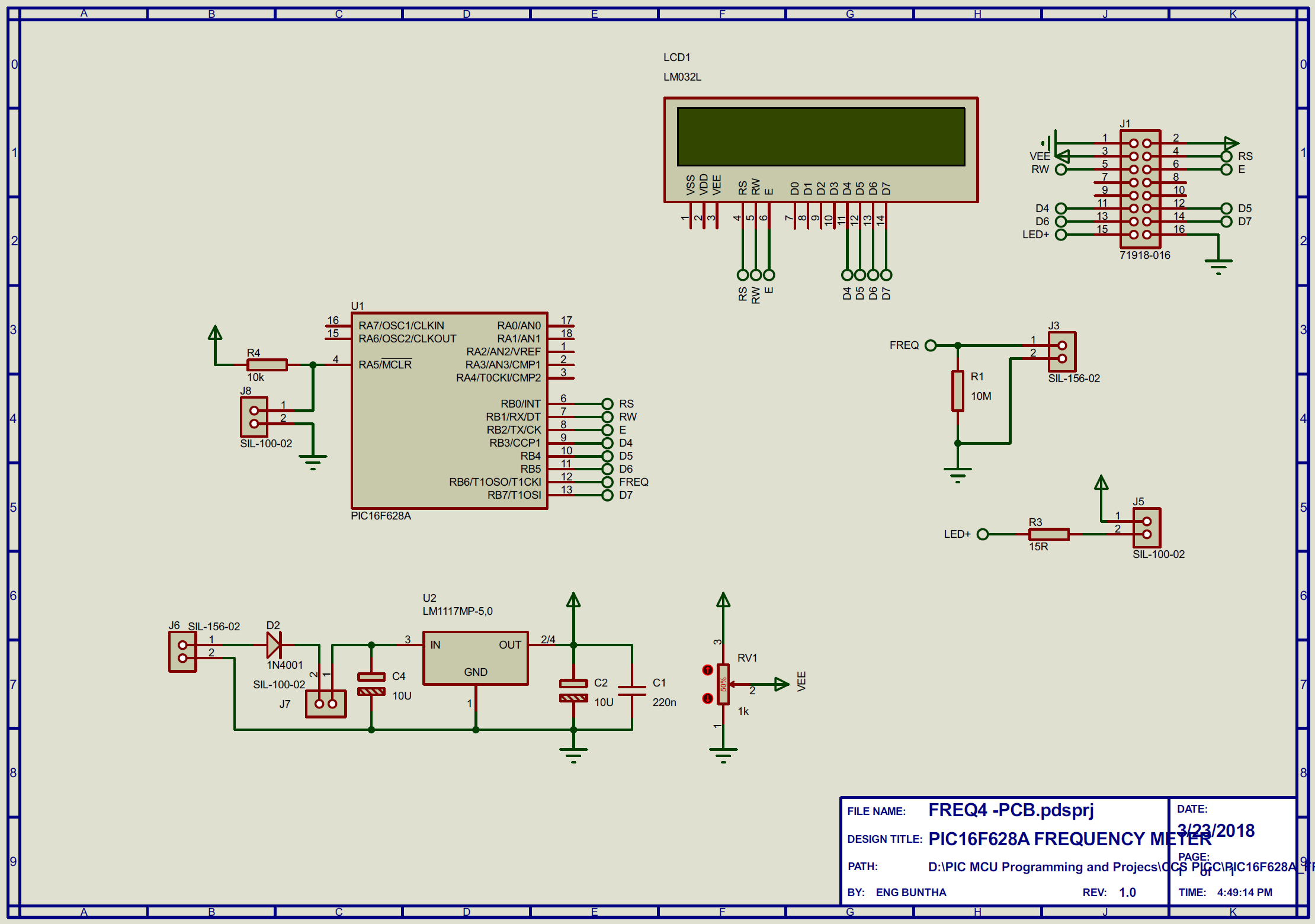
Image galleries:


source archive:
https://github.com/BongPeav/CCS-PICC/raw/master/Frequency_Counter_LCD.rar
There’s a mistake of the period of the frequency in this code. When it measures the frequency of 0Hz, the period shows 0 second. However I don’t have any time to modify them again. The code project attached here is opened. The user can modify this code to the correct one’s.
The PCB project I list above was made by hands. For some professional requirements, we can order a professional PCB service such as PCB Way at a reasonable price. I have made this meter for a few local companies that require electronic measurement.
Order this kit with PCBWay:

CCS PICC code for this example project:
/* THE CPU RUN BY INTERNAL 4MHz CLOCK
*  WE USE TIMER 0 TO MAKE A ONE SECOND DURATION
*  WE USE TIMER 1 TO ACCUMULATE THE TOTAL INPUT PULSE */

#include <16F628A.h>
#fuses INTRC_IO,NOLVP,MCLR
//#fuses WDT
#use delay(clock=4M)

#define ONE_SEC_TICKS 3907
//3907
#define LCD_ENABLE_PIN  PIN_B2
#define LCD_RS_PIN      PIN_B0
#define LCD_RW_PIN      PIN_B1
#define LCD_DATA4       PIN_B3
#define LCD_DATA5       PIN_B4
#define LCD_DATA6       PIN_B5
#define LCD_DATA7       PIN_B7
#include<LCD.c>

volatile unsigned int16 T1=0;
volatile unsigned int16 T0_INT_CNT=0;
volatile unsigned int16 T1_INT_CNT=0;
volatile unsigned int32  FREQ=0;
volatile float  PRD=0;

void main()
{
   LCD_INIT();
   //setup_wdt(WDT_2304MS);
   setup_timer_0(RTCC_INTERNAL|RTCC_DIV_1);
   setup_timer_1(T1_EXTERNAL|T1_DIV_BY_1);
   enable_interrupts(GLOBAL);
   enable_interrupts(INT_TIMER0);
   enable_interrupts(INT_TIMER1);
   clear_interrupt(INT_TIMER0);
   clear_interrupt(INT_TIMER1);
   printf(LCD_PUTC," FREQUENCY METER");
   printf(LCD_PUTC,"\n   Please Wait");
   set_timer1(0);
   set_timer0(0);
   while(TRUE){
      //restart_wdt();
   }
}

#INT_TIMER0
void TMR0_ISR(){
   T0_INT_CNT++;
   if(T0_INT_CNT==ONE_SEC_TICKS){
      T0_INT_CNT=0;
      T1=get_timer1();
      FREQ=make32(T1_INT_CNT,T1);   // make 32 bit value of input pulses
      PRD=(1000000.0/FREQ)*1000;    // nanoseconds   range

      ///////////////////////////////////////////////////////
      printf(LCD_PUTC,"\ff : %Lu Hz\n",FREQ);

      if(PRD<1000)
         printf(LCD_PUTC,"T : %0.3f nS",PRD);
      else if(PRD>1000&&PRD<1000000){
         PRD/=1000;
         printf(LCD_PUTC,"T : %0.3f uS",PRD);
      }
      else {
         PRD/=1000000;
         printf(LCD_PUTC,"T : %0.3f mS",PRD);
      }

     /////////////////////////////////////////////////////////////


      T1_INT_CNT=0;

   }
   clear_interrupt(INT_TIMER0);
}

#INT_TIMER1
void TMR1_ISR(){
   T1_INT_CNT++;
   clear_interrupt(INT_TIMER1);
}
Any suggestion relates to this post could be sent to the author using the contact form below.