PIC16F877A/887 Programming Tutorials In MikroC

PIC16F877A is an old 8-bit PIC device release around 2003. Many new released 8-bit PIC devices come with many special features and rich of peripheral.

Copy Microcontroller PIC16F887 File

However, PIC16F877 is still in use for student to start learning PIC programming.

MikroC Pro for PIC is a C compiler targeting the 8-bit PIC device. It has a free version, but it limit the coding size to not above 2 KB.

I have wrote some beginning tutorials for PIC16F877A with MikroC:

  1. Getting started with MikroC
  2. Digital Ports programming and interfacing

For PIC16F887 in MikroC

  1. Blinking the PIC16F887 in MikroC
  2. Using PORTA of PIC16F887 as a digital I/O
  3. PIC16F887 toggling an output relay
  4. Using PORTB internal resistors of PIC16F887 in MikroC
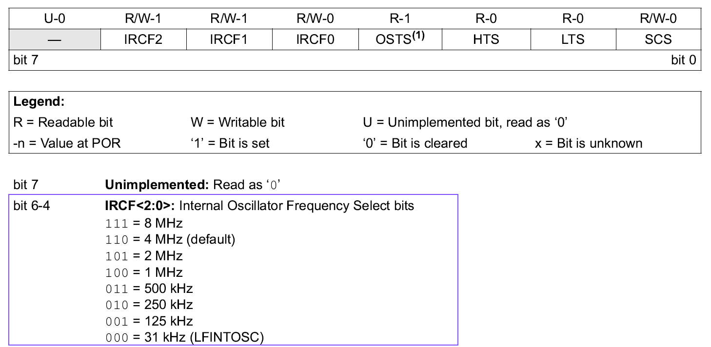
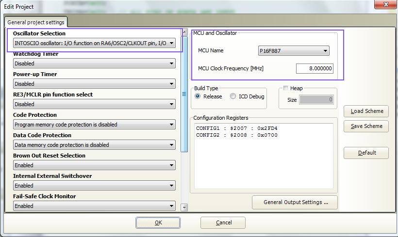
  5. Accessing the internal 8 MHz oscillator of PIC16F887 in MikroC
  6. PIC16F887 External Interrupt Example With 7-Segments Display In MikroC
  7. PIC16F887 Interrupt-On-Change in MikroC
  8. PIC16F887 IOCB in motor control example using MikroC
  9. PIC16F887 Timer0 Works in Counter Mode MikroC
  10. PIC16F887 Timer0 in timer mode MikroC
  11. PIC16F887 Timer0 Interrupt Programming in MikroC
  12. PIC16F887 Timer0 Creating Delay Function in MikroC
  13. PIC16F887 Timer0 Interrupt Driven Display
  14. PIC16F887 Timer1 and Ultra Sonic Range Measurement Application

Making a low speed frequency meter using MikroC

Frequency meter can be made using a simple method, but this method could measure a low frequency range. It’s suitable for any application at the system that process with a low frequency input.

I use a C-loop to measure the input frequency. The loop repeats at 55800 times making a one-second period. during this period if the input state is High that will increase the counter.

1
The signal is being fed to pin RC0. While PORTB is use for output LCD driving.

code archive:

https://github.com/BongPeav/MikroC-8-bit-PIC/raw/master/PIC16F876A_LOWSPEED_FREQ.rar

MikroC source code for PIC:

// LCD module connections
sbit LCD_RS at RB4_bit;
sbit LCD_EN at RB5_bit;
sbit LCD_D4 at RB0_bit;
sbit LCD_D5 at RB1_bit;
sbit LCD_D6 at RB2_bit;
sbit LCD_D7 at RB3_bit;

sbit LCD_RS_Direction at TRISB4_bit;
sbit LCD_EN_Direction at TRISB5_bit;
sbit LCD_D4_Direction at TRISB0_bit;
sbit LCD_D5_Direction at TRISB1_bit;
sbit LCD_D6_Direction at TRISB2_bit;
sbit LCD_D7_Direction at TRISB3_bit;
// End LCD module connections

#define FREQ_IN PORTC.RC0    // USE RC0 AS FREQUENCY SOURCE

void main() {
     unsigned long freq=0;
     unsigned long i;
     unsigned char freq_data[12];   // used to store string
     TRISC=0xFF;   // PORTC AS INPUT
     PORTC=0x00;   // CLEAR PORTC
     Lcd_Init();
     Lcd_Cmd(_LCD_CURSOR_OFF);   // TURN OFF CURSOR
     Lcd_Out(1,4,"PIC16F876A");
     Lcd_Out(2,2,"FREQUENCY METER");
     delay_ms(1000);
     Lcd_Cmd(_LCD_CLEAR);
     Lcd_Out(1,1,"FREQUENCY (Hz)");
     while(1){
       for(i=0;i<55800;i++){
         if(FREQ_IN==1){ while(FREQ_IN==1); freq++;}
       }
     IntToStr(freq,freq_data);
     Lcd_Out(2,1,freq_data);
     freq=0;
     }
}

Any suggestion relates to this post could be sent to the author using the contact form below.

A temperature display using PIC16F716 and LM35 with MikroC and Proteus 8

LM35 is an analog temperature sensor. The output temperature data is +10mV per degree Celsius. Typically It come with TO-92 transistor-like package.

TO92
LM35 temperature sensor with TO-92 Package

We commonly use it on board with microcontroller to measure temperature for example for controlling DC fan.

In this project I make temperature display board using LM35 and PIC16F716 along with seven segment display (SSD). There are many popular PIC device with built-in ADC, but I posses only PIC16F716. It has an 8-bit ADC module inside. I use 2.5V voltage reference adjusted from a POT to decrease the ADC step size for 8-bit ADC.

The SSD is multiplexed together due to I/O pins limited.

Schematic:

SSD

The CPU run at the speed 11.0592Mhz that I posses.  The ADC conversion run very fast so it will consume a lot energy and the display will become rough. I use timer0 interrupt to schedule the ADC reading to 1 time per second.

Source from GitHub:

https://github.com/BongPeav/MikroC-8-bit-PIC/raw/master/16F716_LM35_SSD.rar

MikroC source code:

// PIC16F716 LM35 SSD
// CLOCK 11.0592MHz
// FMC 2764800 MIPS
// TMC 361 ns
// TIMER0 RATE 1:256 = 92416 ns = 92.416 us
// TIMER0 INTERRUPT : 92.416 us * 256 = 23658 us = 23.658 ms
// ADC CLOCK = INTERNAL RC
// ADC CHANNEL = RA0
// VREF = RA3 2.6V

unsigned short cnt=0;
unsigned  temperature=0;
unsigned D1=0,D0=0;
bit read;
unsigned char SSD_MAP[10]={0xC0,0xF9,0xA4,0xB0,0x99,0x92,0x82,0xF8,0x80,0x90} ;

unsigned short get_lm35(){
  ADCON0.GO_DONE=1; // start read
  while(ADCON0.GO_DONE);
  return ADRES;
}

void SSD() {

     temperature=100*(ADRES)*2.5/256;
     D1=temperature/10;
     D0=temperature%10;
     PORTB=SSD_MAP[D1];
     PORTA=0x02;
     delay_ms(10);
     PORTA=0x00;
     
     PORTB=SSD_MAP[D0];
     PORTA=0x04;
     delay_ms(10);
     PORTA=0x00;
     
     PORTB=0x9C;
     PORTA=0x10;
     delay_ms(5);
     PORTA=0x00;

     PORTB=0xC6;
     PORTB|=0x80;
     delay_ms(5);
     PORTB&=0x7F;
}

void interrupt(){
     if(INTCON.T0IF) {
        cnt++;
        if(cnt==50)
        { cnt=0;
          get_lm35();
        }
     }
     INTCON.T0IF=0;
}

   
void main() {

     PORTB=0x00; // CLEAR PORTB
     PORTA=0x00; // CLEAR PORTA
     TRISA=0x09; // RA0 AND RA4 AS INPUT
     TRISB=0x00; // PORTB AS OUTPUT
     OPTION_REG.T0CS=0;   // SELECT TIMER0
     OPTION_REG.PSA=0;    // PRESCALER ASSIGNED TO TIMER0
     OPTION_REG&=0x07;    // SELECT 1:256
     INTCON.GIE=1;        // ENABLE GLOBAL INTERRUPT
     INTCON.T0IE=1;       // TIMER0 INTERRUPT ENABLE
     ADCON1=0x05; // RA0 ANALOG RA3 VREF
     ADCON0.ADCS0=1;
     ADCON0.ADCS1=1; // SELECT INTERNAL RC
     ADCON0.CHS0=0;
     ADCON0.CHS1=0;
     ADCON0.CHS2=0;  // SELECT CHANNEL 0
     ADCON0.ADON=1; // ENABLE ADC
     INTCON.T0IF=0;    // CLEAR FLAG
     get_lm35();
     TMR0=0;
     while(1)
     SSD();

}

See also:

Any suggestion relates to this post could be sent to the author using the contact form below.

Using internal RC of PIC16F887 in MikroC

Introduction

PIC16F887 is a good replacement for PIC16F877A. They have common features but PIC16F887 has many more extended features. In this section show one feature of internal calibrated RC oscillator in PIC16F887 that PIC16F877A doesn’t have.

There are two internal oscillators: LFINTOSC and HFINTOSC. LFINTOSC is a low speed oscillator running at 32kHz. HFINTOSC is a high speed oscillator running at range from 1MHz to 8MHz.

The frequency of internal oscillator is selected by Oscillator control register (OSCCON) of the SFR. Other register called OSCTUNE ( Oscillator Tuning Register) is optional and we use it tune to any frequency ranging from 31kHz to 8MHz.

Similarly, other C compiler could be written to get access to the internal oscillator like here. Some PIC users like XC8 C compiler. They made a similar program I did here.

Writing the program

We select the frequency using OSCCON register.

OSCCON

What we have to do with OSCCON is bit 6-4. The 3-bit long IRCF<2:0) (Internal Oscillator Frequency Select bit) allows us to select the frequency between 31kHz to 8MHz. In this example we select 8MHz so the IRCF mus be 111 in binary or 0x07 in hex.

In MikroC IDE starts a new project. In the project menu select Project -> Edit Project . We will see the Edit Project Windows and give the setting to project as follow:

edit-project

In Oscillator Selection, choose INTOSCIO. In MCU and Oscillator select P16F887 and MCU Clock 8MHz.

The program below is the shift LED on PORTA of PIC16F887 using internal oscillator running at 8MHz.

Here is schematic.

16F887_INTRC_IO

Attached is the full work of this article.

In the code editor windows write the code below:

/* USING INTERNAL OSCILLATOR OF
PIC16F887
AUTHOR: ENG BUNTHA */

void main() {
     char LED;
     PORTA=0x00;
     TRISA=0x00;   // ALL PINS ON PORTA ARE INPUT
     OSCCON.IRCF0=1;
     OSCCON.IRCF1=1;
     OSCCON.IRCF2=1;  // SELECT INTERNAL OSC RUNNING AT SPEED 8MHz
     
     while(1) {
              LED=0x01;
              while(LED!=0x00) {
                               PORTA=LED;
                               delay_ms(100);
                               LED<<=1;      // SHIFT LEFT ONE TIME
                               }
              }
}