Multi digits display
Multiplexed seven segment display is capable of driving fewer digit around 6 digits. Things become worse when we try to multiplex many digits for example 10 digits.
In convenience we use serial transmission method for sending data to each digits. Each digits are independence and are driven by individual shift register. Each shift register connects to each other via two line: serial data line and serial clock line.
Introduction To SN74HC595 IC
74HC595 is a popular IC widely use with microcontroller to receive serial data from microcontroller. It’s a serial in / parallel out shift register. It’s CMOS type. The output data is 8-bit wide. And it has a serial data out pin to shift data to next external register.
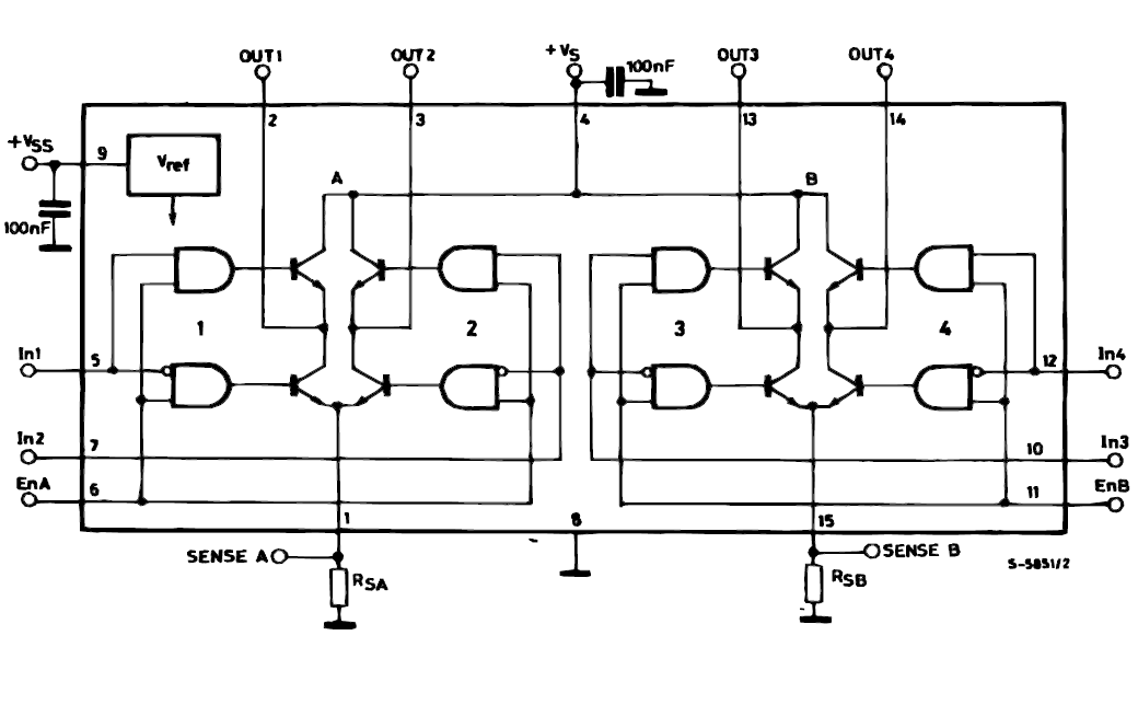
The block diagram below show the function diagram of 74HC595.
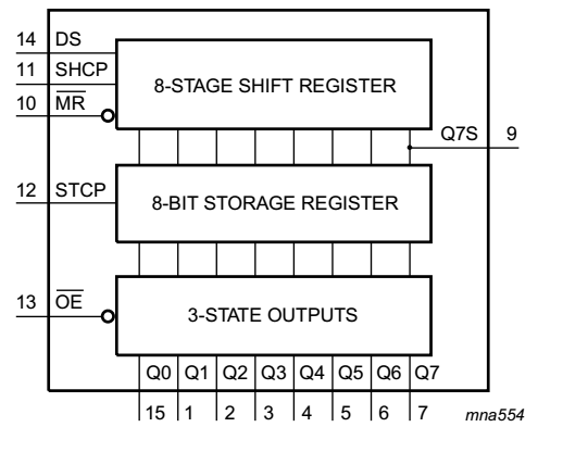
Data is shifted in to the shift register via serial data line (DS) synchronizes with serial clock line (SHCP). /MR is the reset signal it must connected to Vcc in normal operation. Q7S is a serial data pin that shift data out to next IC.
Data is latched into storage register via internal parallel data lines when storage register clock (STCP) pin is active ( Low to High).
Output register shift data out in parallel to outside world. It usually connect to LEDs, seven segment display or relay ,etc. The /OE pin controls the output of output register. It must connect to ground to enable the outputs.
The output data is 8-bit wide ranging from Q0 to Q7.
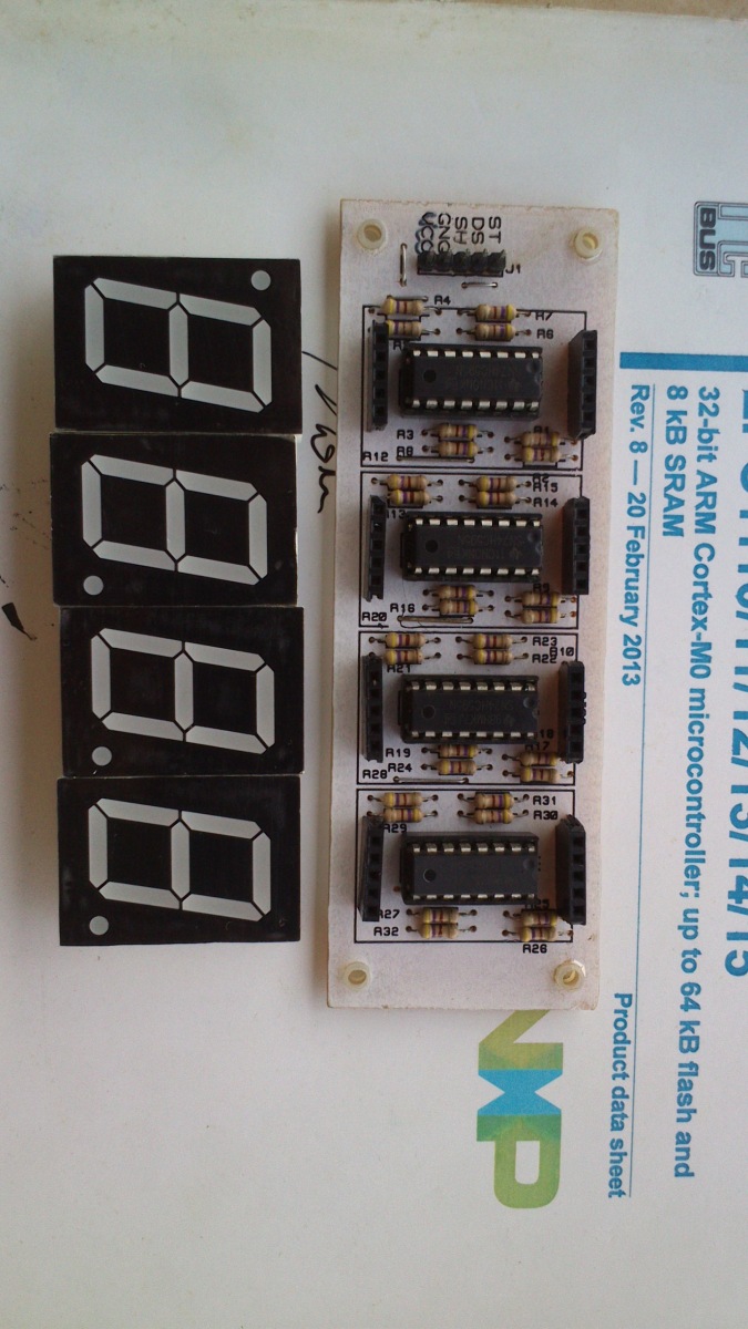
Serial display board design
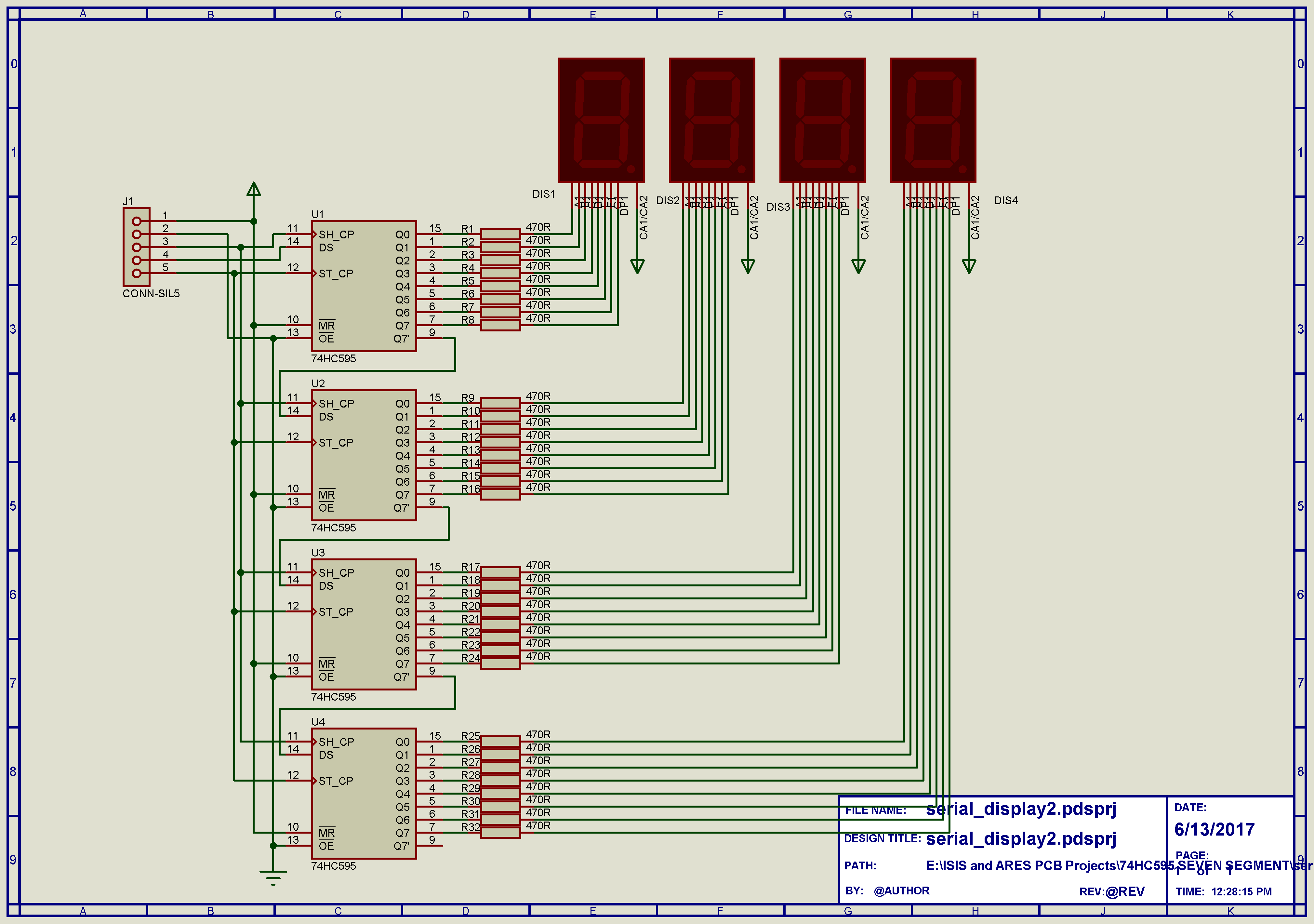
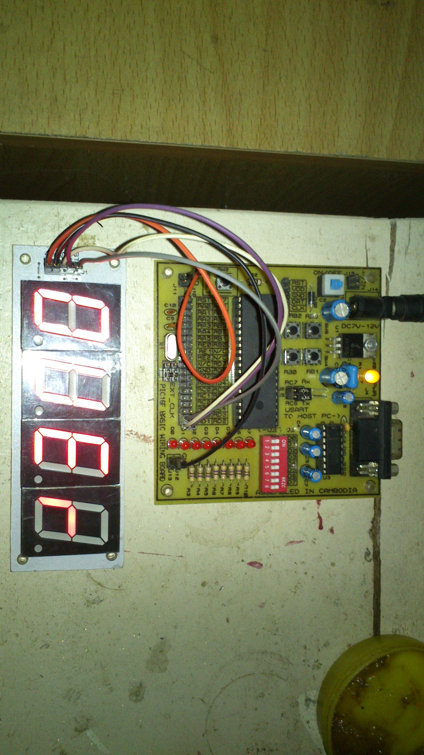
In this project I create seven segment board that consist of 7 digits. Each digit is red in color, 1 inch diagonal and common cathode type. Data is shift into this module serially via three wires: serial data (DS), serial clock (SHCP) and storage clock (STCP). First IC connect to next IC via two wire: serial data output (Q7S) and serial clock (SHCP). STCP is common to all ICs. It’s commonly use with +5V logic level.
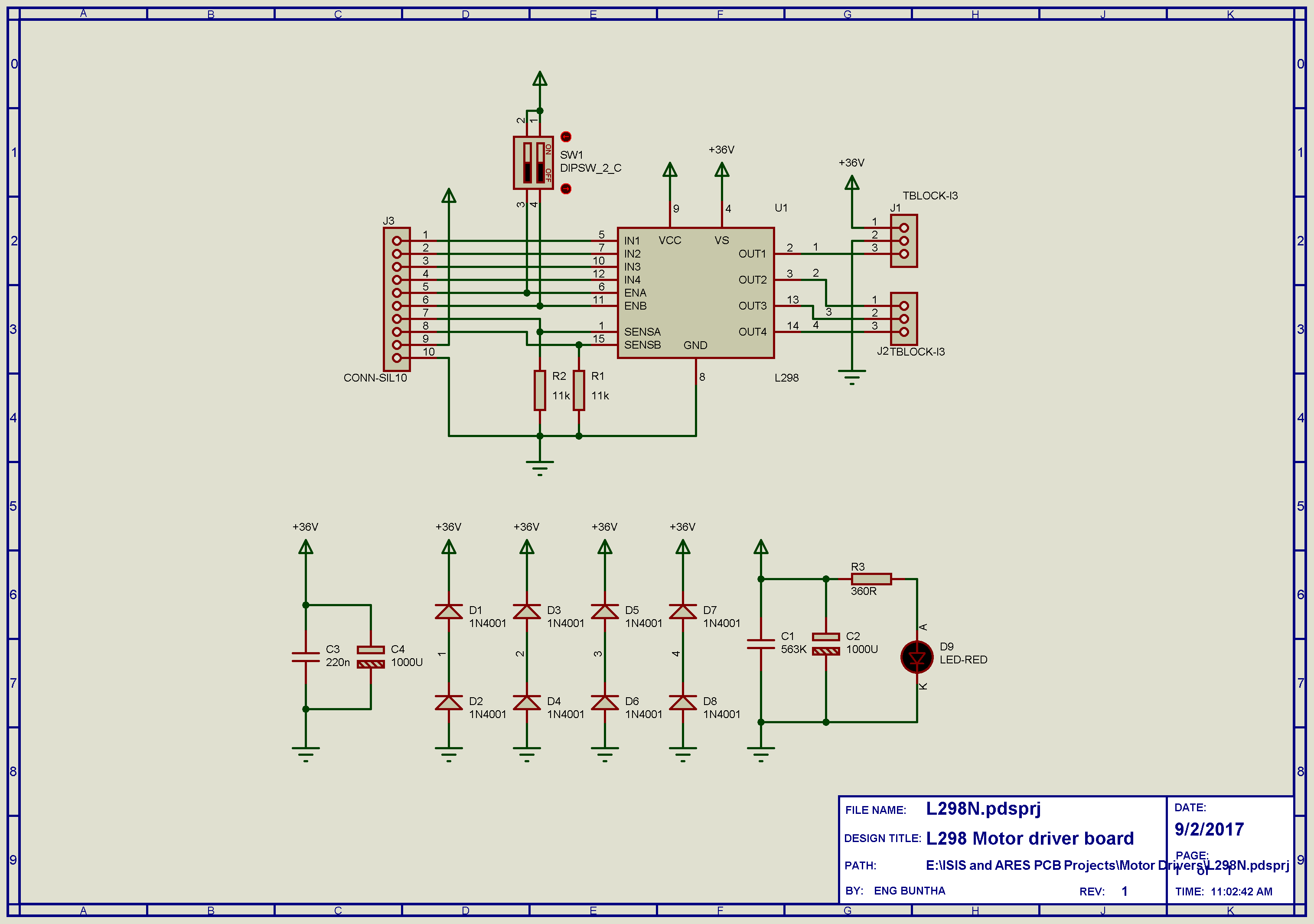
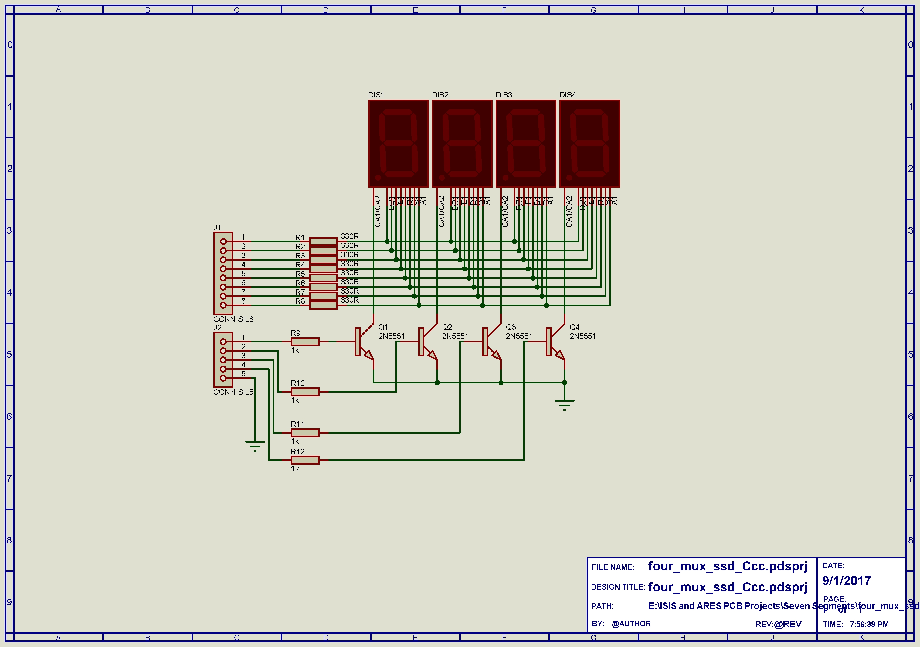
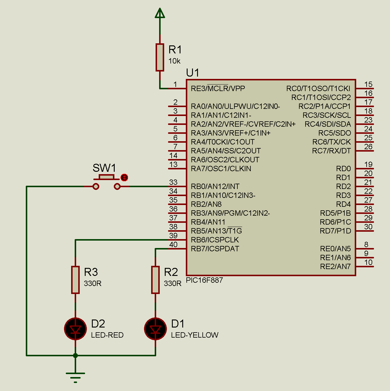
Let see the schematic below:
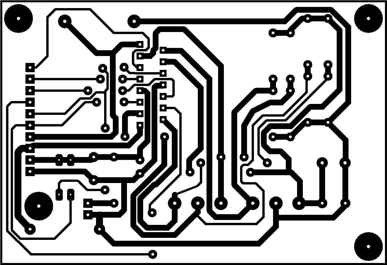
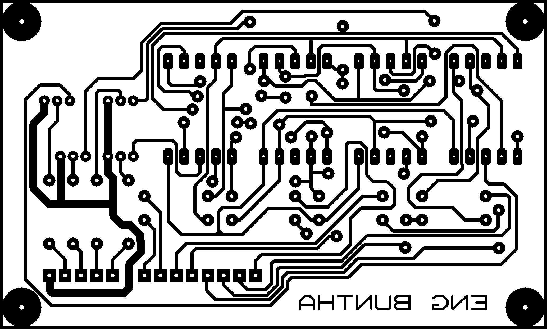
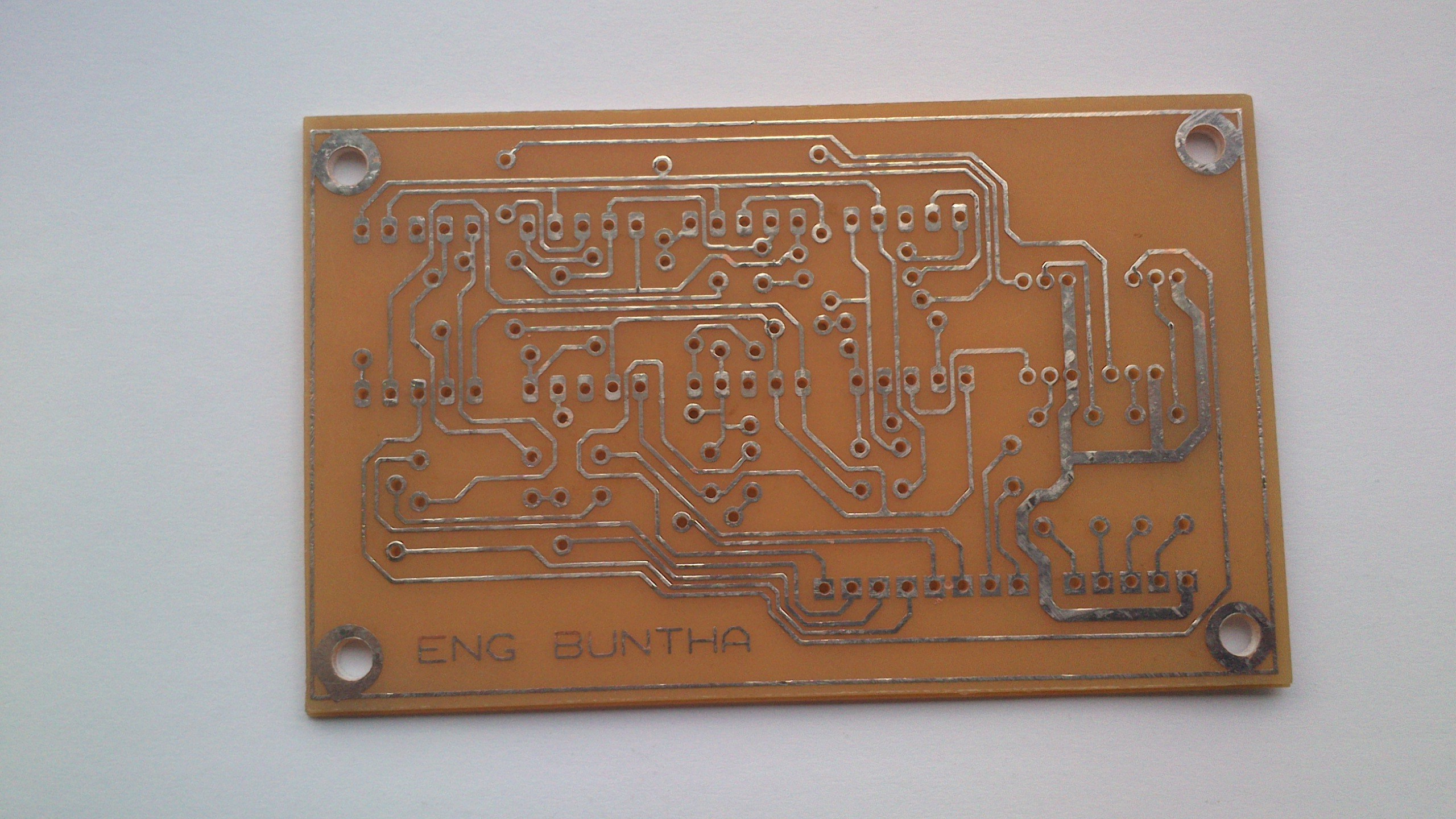
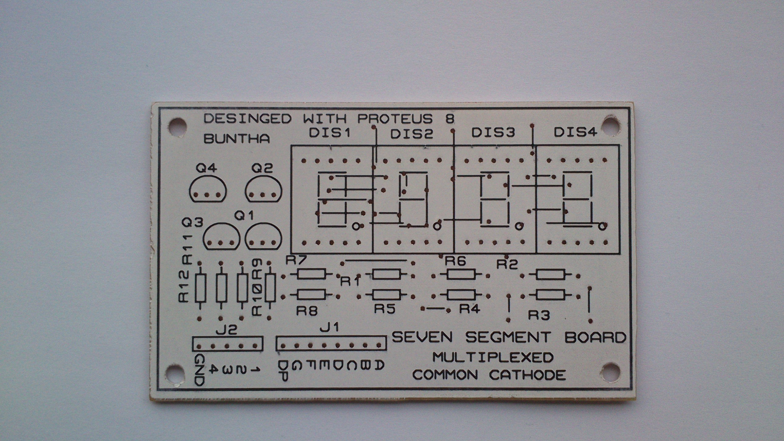
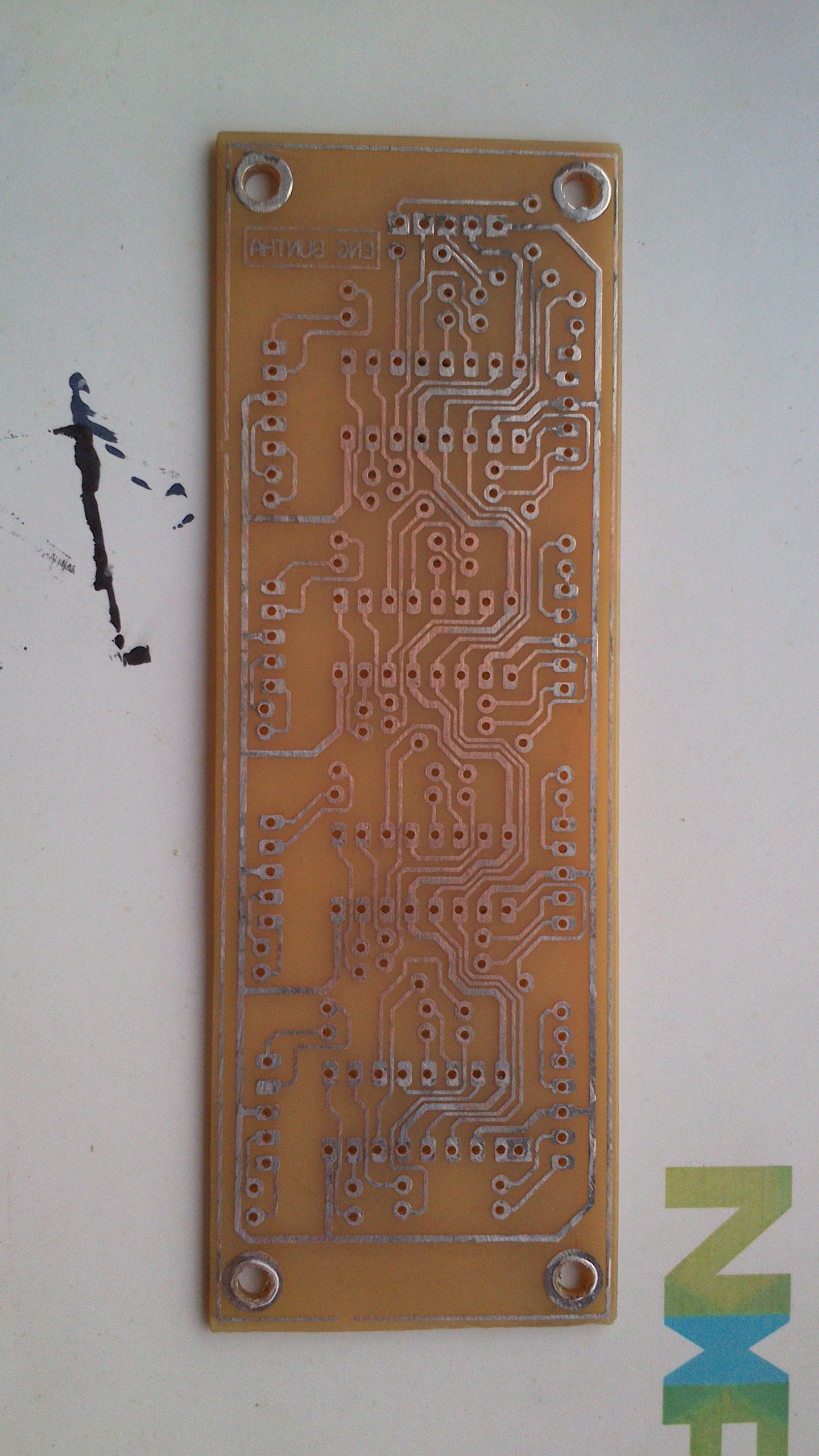
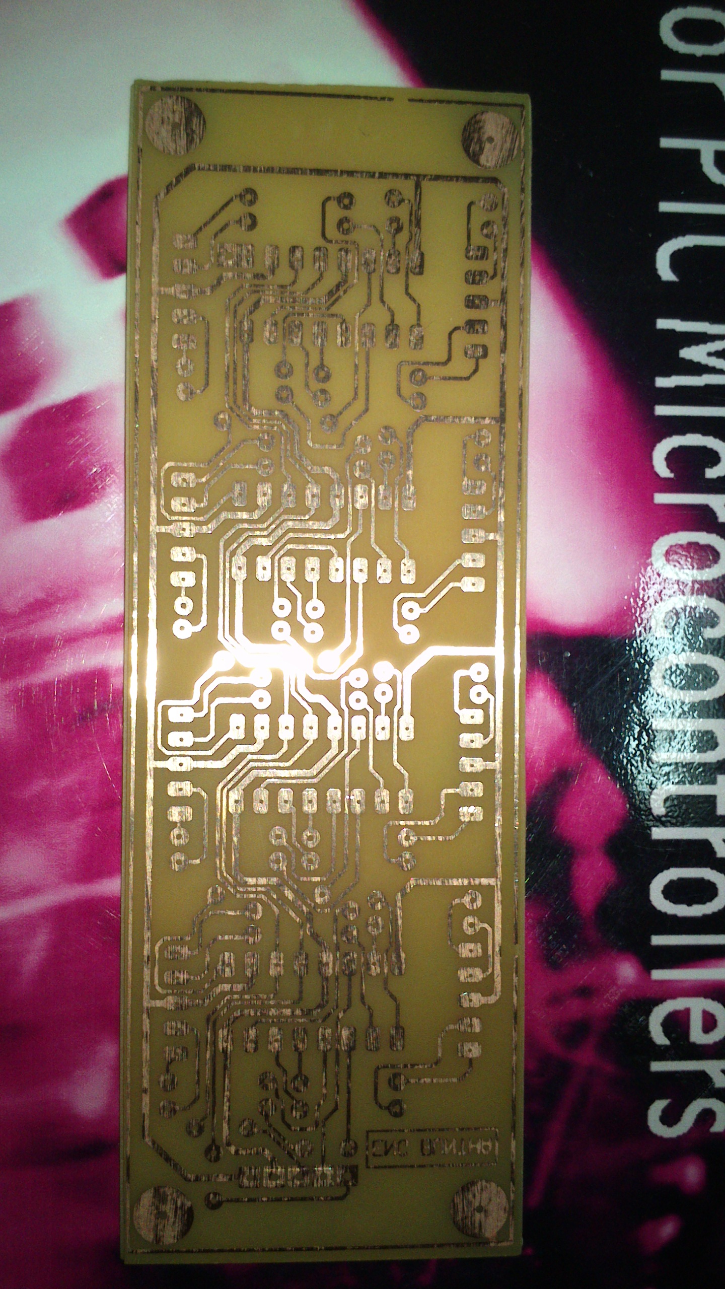
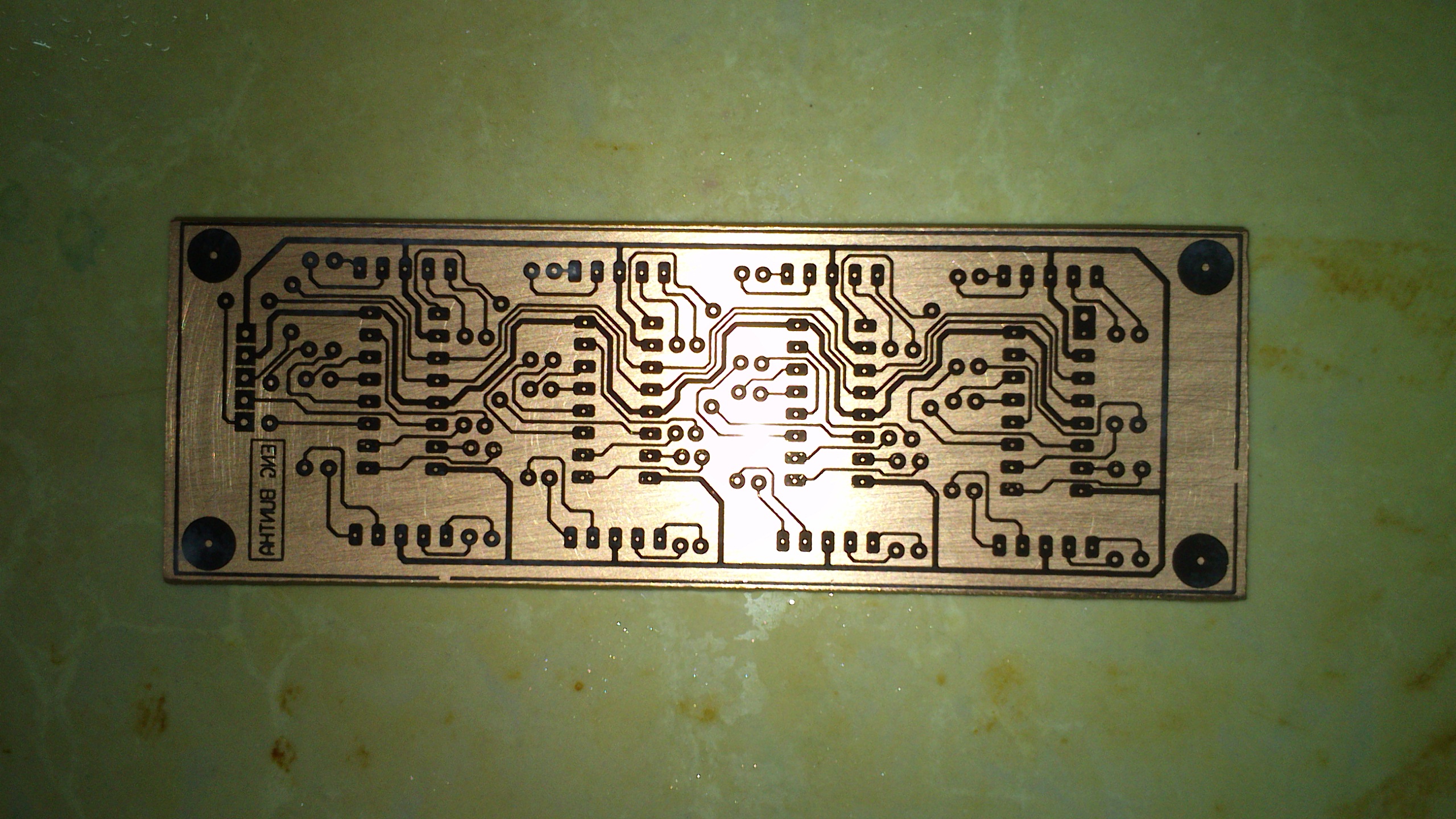
The PCB is single sided board with some jumpers.
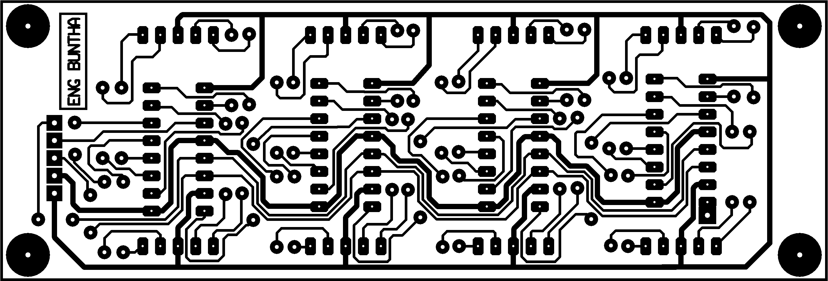
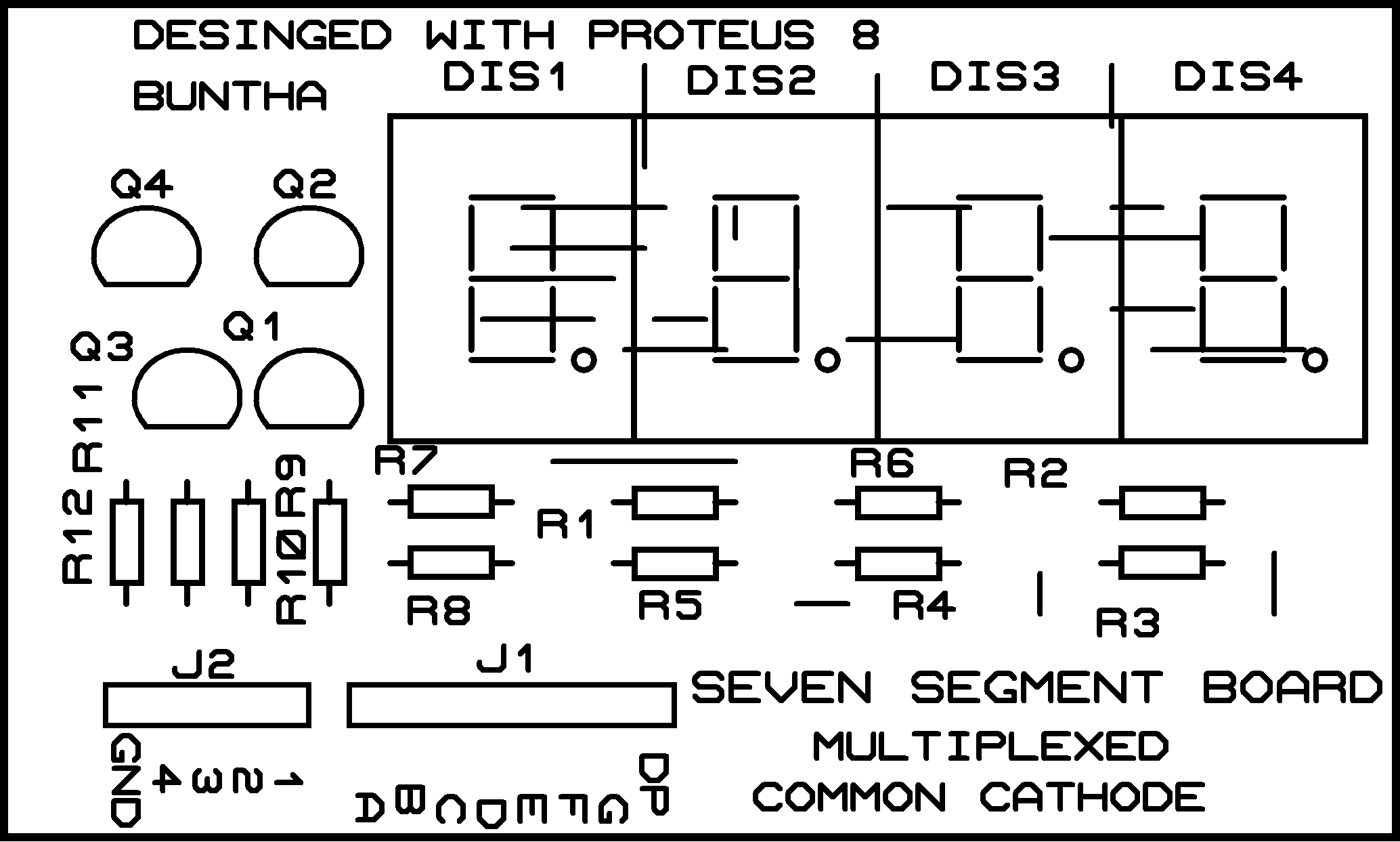
I create the design file with Proteus 8.5 SP0. You can download it here.
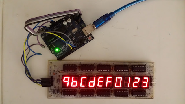
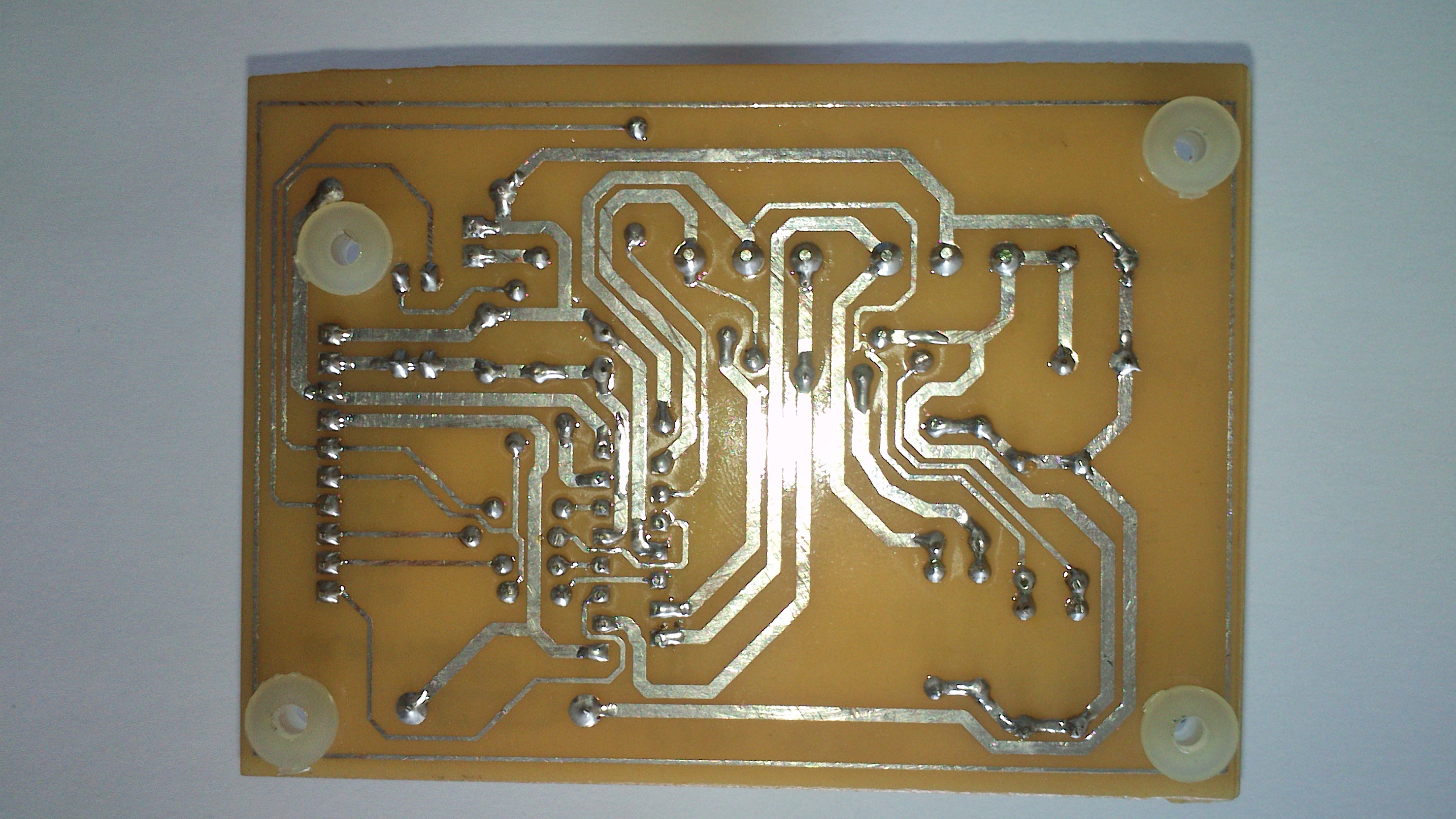
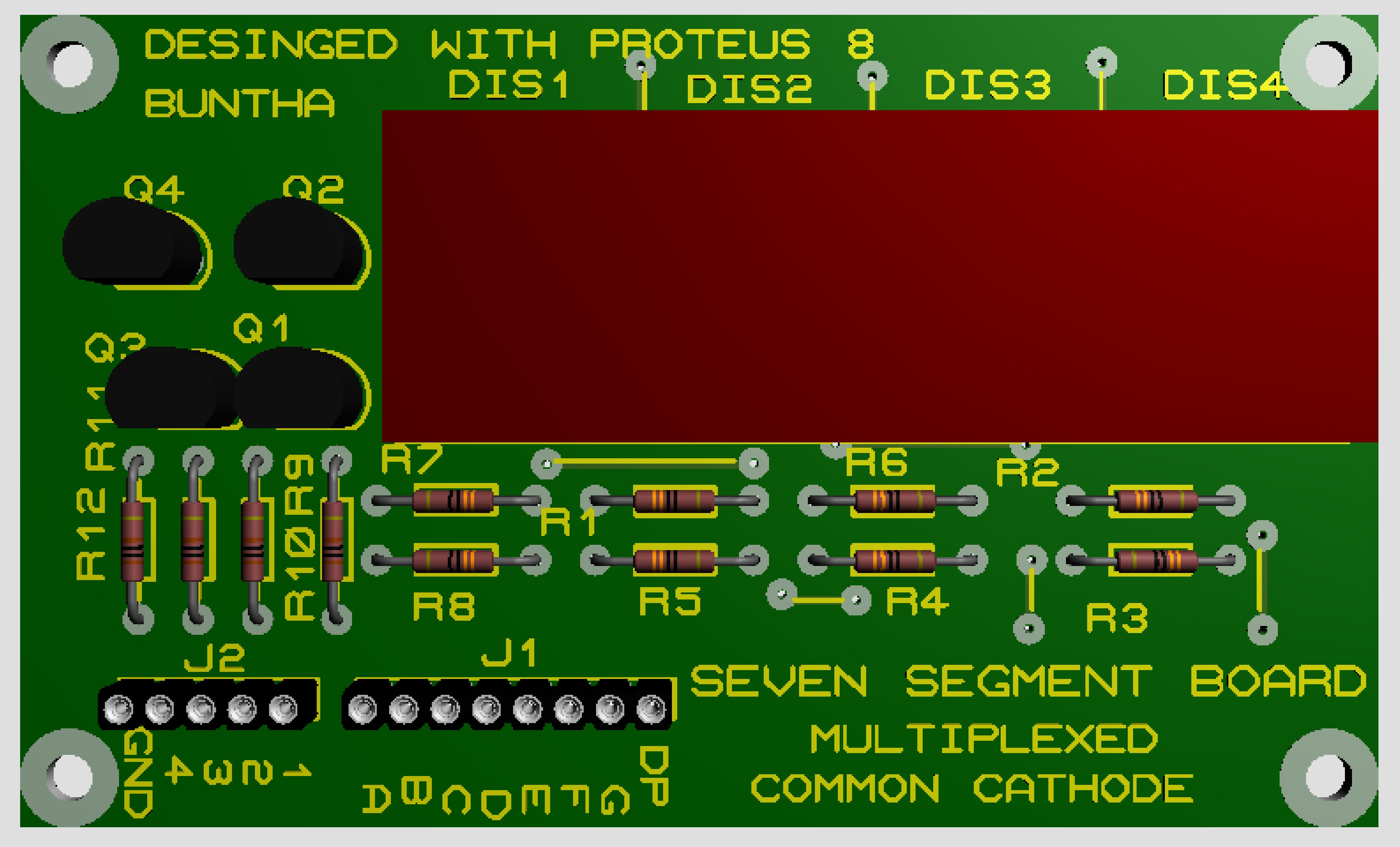
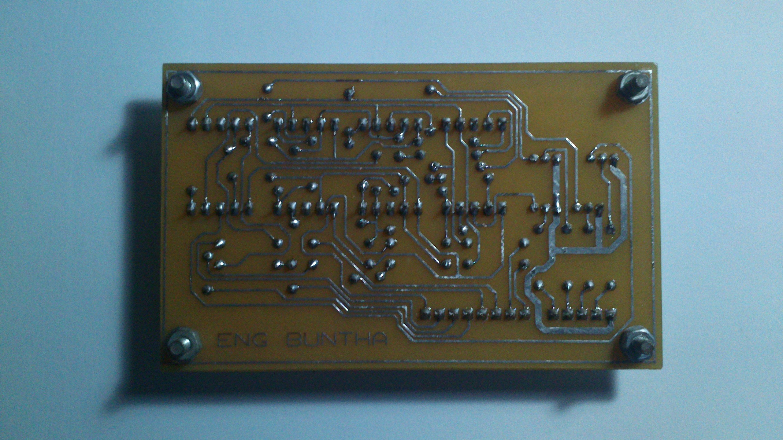
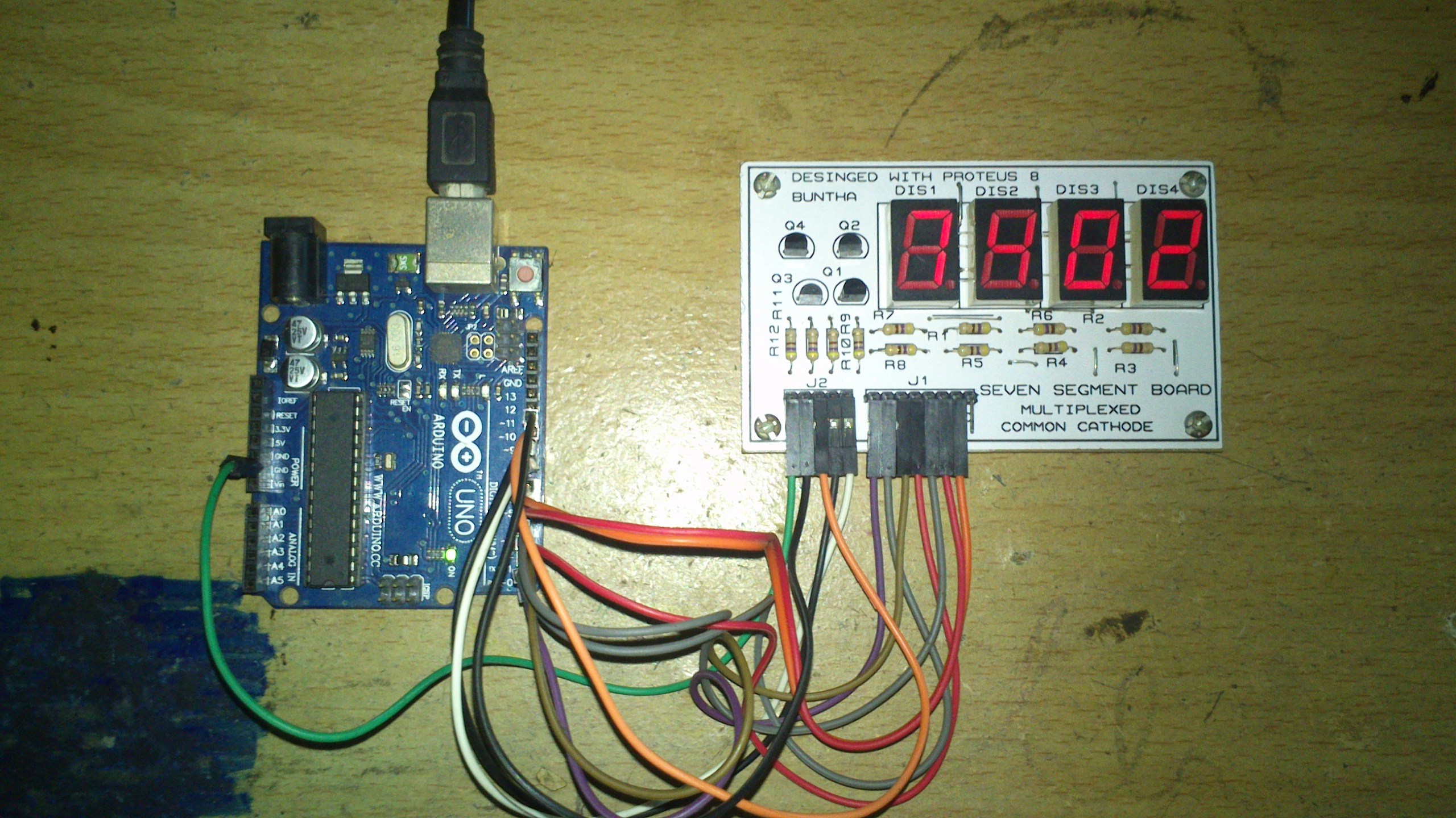
The galleries below shows the complete work of this project.


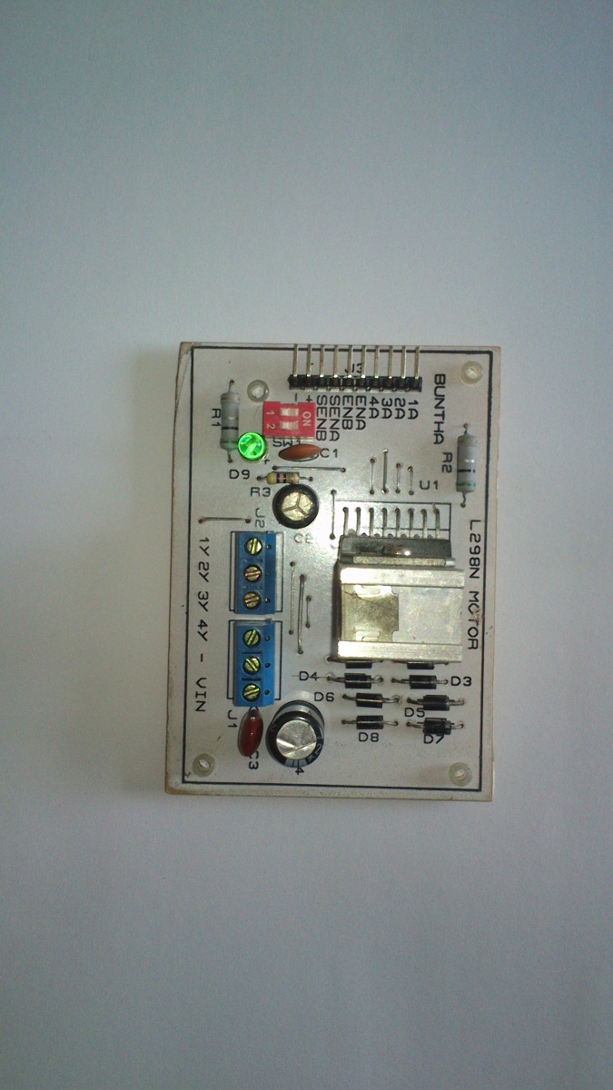
For a larger display with DIY PCB you can see this PCB design.