
Digital Volt Meter (DVM) could be built from scratch using any ADC IC such as ICL7107 or ICL7135. However those IC have a large pin counts requiring us more time to wire.
Using a microcontroller we can reduce the number of pin count for the display. A common way is using multiplexed display.
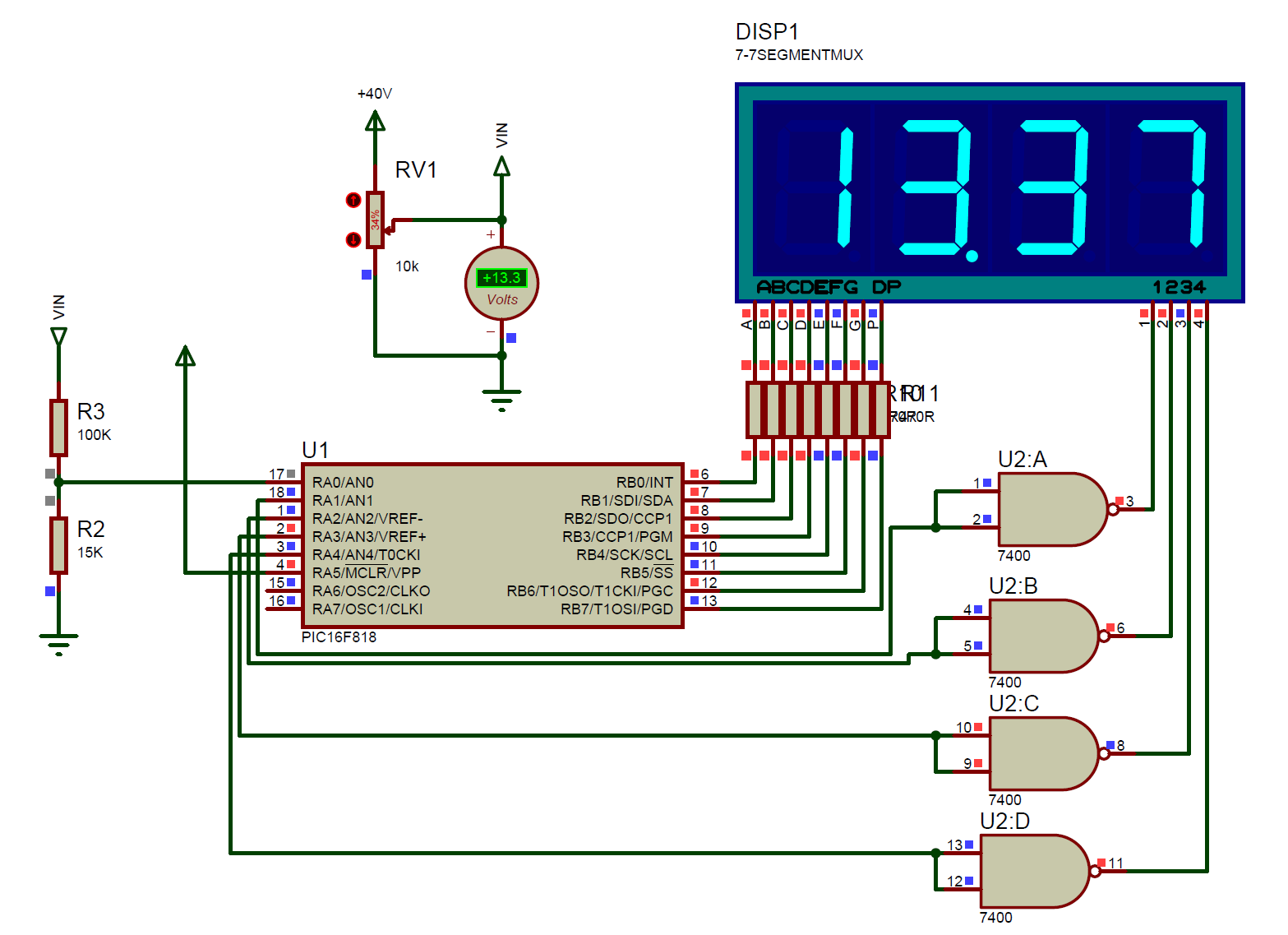
In this project I use PIC16F818 with a 10-bit built-in ADC to read analog voltage range from 0 to +40V DC.
ADC work only with +5V. So I use the voltage divider rule to reduce the scale of input voltage. As show in the schematic below, the resistors R3 and R2 are use for voltage divider. From voltage divider rule I get the scale factor of 0.13.
Download this source from GitHub:
https://github.com/BongPeav/CCS-PICC/raw/master/16F818_timer0_ADC_DVM_0_35V.rar
CCS PICC source code for this example:
// PIC16F818 DVM

#include <16f818.h>
#DEVICE ADC=10
#fuses INTRC_IO,NOWDT,NOLVP,NOPUT,NOBROWNOUT
#use delay(clock=4M)

#define LED_DELAY delay_ms(5)

unsigned int16 reader;
unsigned int8 counter;
unsigned int8 number[10]={0x3F,0x06,0x5B,0x4F,0x66,0x6D,0x7D,0x07,0x7F,0x6F};

float voltage;

#int_timer0
void timer0isr()
{
  counter++;
}

///////////////////////////////////
void displaydata(float raw){
   unsigned int16 dig4,dig3,dig2,dig1,data,temp1,temp2;
   float mydat;
   mydat=raw*100;
   data=mydat;
   dig4=data/1000;
   temp1=data%1000;
   dig3=temp1/100;
   temp2=data%100;
   dig2=temp2/10;
   dig1=data%10;
  //////////////////////////////////////////
   output_B(number[dig4]);
   output_high(PIN_A1);
   LED_Delay;
   output_low(PIN_A1);
   ///////////////////////
   output_B(number[dig3]|0x80);
   output_high(PIN_A2);
   LED_DELAY;
   output_low(PIN_A2);
   ////////////////////////////////
   output_B(number[dig2]);
   output_high(PIN_A3);
   LED_DELAY;
   output_low(PIN_A3);
   ///////////////////////////
   output_B(number[dig1]);
   output_high(PIN_A4);
   LED_DELAY;
   output_low(PIN_A4);
}

void main()
{
   SET_TRIS_B(0x00);
   SET_TRIS_A(0x01);
    SETUP_ADC(ADC_CLOCK_DIV_2);
   SETUP_ADC_PORTS(ALL_ANALOG);
   SET_ADC_CHANNEL(0);
   DELAY_US(30);
   SETUP_TIMER_0(RTCC_DIV_256);
   ENABLE_INTERRUPTS(GLOBAL);
   ENABLE_INTERRUPTS(INT_TIMER0);
   CLEAR_INTERRUPT(INT_TIMER0);
   while(TRUE)
   {
      //TODO: User Code
   //  if(counter==5){
   //  counter=0;
      reader=read_adc();
      while(!adc_done());
      voltage=(reader*(5.0/1024))/0.130;
  //    }
      displaydata(voltage);
   }

}
Any suggestion relates to this post could be sent to the author using the contact form below.
