PIC16F877A/887 Programming Tutorials In MikroC

PIC16F877A is an old 8-bit PIC device release around 2003. Many new released 8-bit PIC devices come with many special features and rich of peripheral.

Copy Microcontroller PIC16F887 File

However, PIC16F877 is still in use for student to start learning PIC programming.

MikroC Pro for PIC is a C compiler targeting the 8-bit PIC device. It has a free version, but it limit the coding size to not above 2 KB.

I have wrote some beginning tutorials for PIC16F877A with MikroC:

  1. Getting started with MikroC
  2. Digital Ports programming and interfacing

For PIC16F887 in MikroC

  1. Blinking the PIC16F887 in MikroC
  2. Using PORTA of PIC16F887 as a digital I/O
  3. PIC16F887 toggling an output relay
  4. Using PORTB internal resistors of PIC16F887 in MikroC
  5. Accessing the internal 8 MHz oscillator of PIC16F887 in MikroC
  6. PIC16F887 External Interrupt Example With 7-Segments Display In MikroC
  7. PIC16F887 Interrupt-On-Change in MikroC
  8. PIC16F887 IOCB in motor control example using MikroC
  9. PIC16F887 Timer0 Works in Counter Mode MikroC
  10. PIC16F887 Timer0 in timer mode MikroC
  11. PIC16F887 Timer0 Interrupt Programming in MikroC
  12. PIC16F887 Timer0 Creating Delay Function in MikroC
  13. PIC16F887 Timer0 Interrupt Driven Display
  14. PIC16F887 Timer1 and Ultra Sonic Range Measurement Application

Making a 8051 basic test board using AT89S52

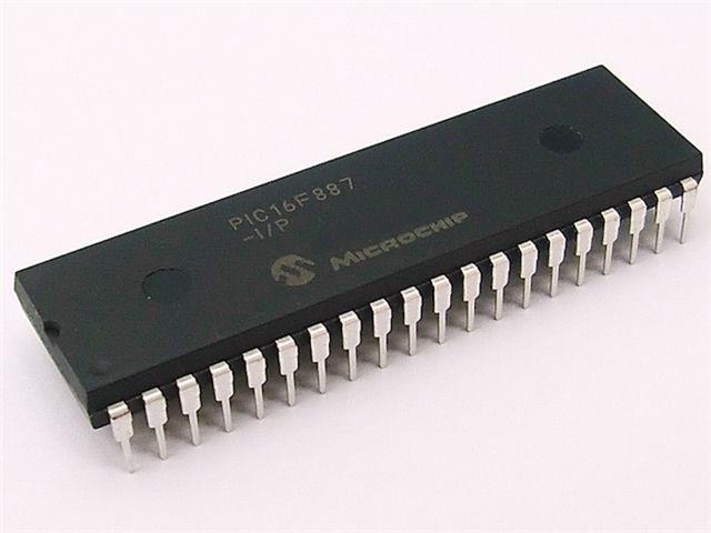
The 8051 microcontroller have been using for along time ago. ATMEL 8051 is a popular 8051 architecture compare to its original vendor Intel. The AT89S52 is a flash ISP version with ease of use.

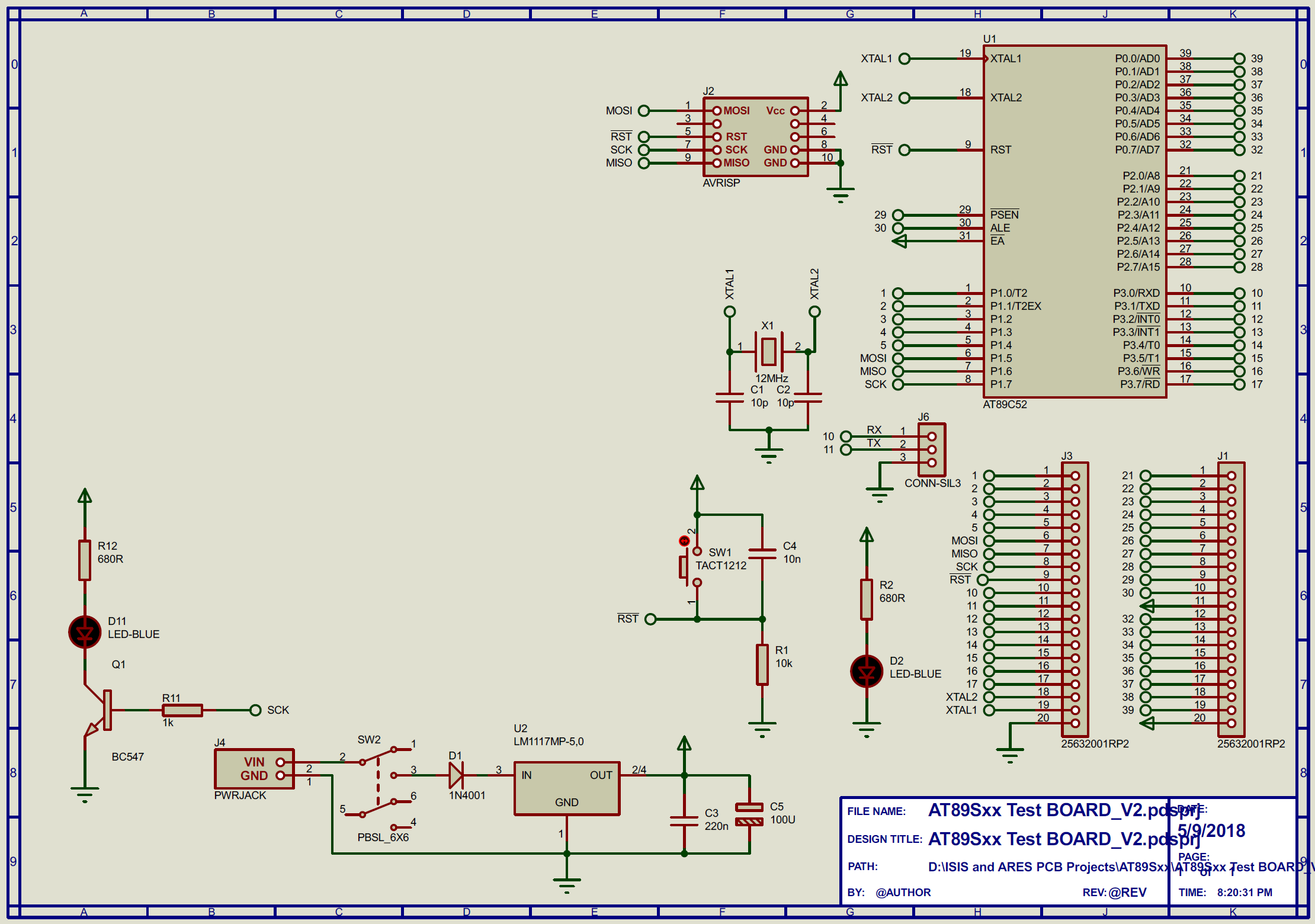
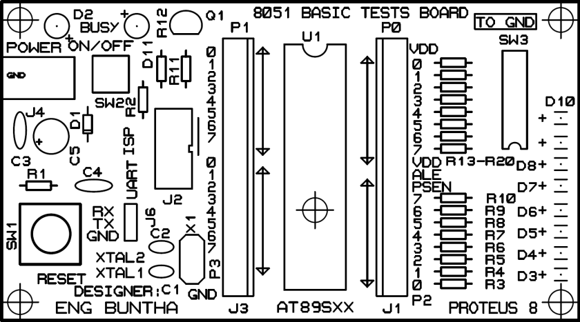
I made a basic test board for this device with low component counts. This prototyping board contains:

  1. On board +5V regulated DC supply
  2. Header for output side device interfacing
  3. Clock and reset circuit
  4. ICSP header to fit usbasp USB programmer
  5. DIP switch and LED

sch

PCB artworks:

copper

silk

source:

https://github.com/BongPeav/Proteus-PCB-Design-files/raw/master/AT89Sxx%20Test%20BOARD_V2.rar

Photo Galleries:

This slideshow requires JavaScript.

This board have been using for my own prototyping at my electronic workshop. I shared this PCB project in the PCB service website.

Designing a digital voltmeter using PIC16F818 built-in ADC

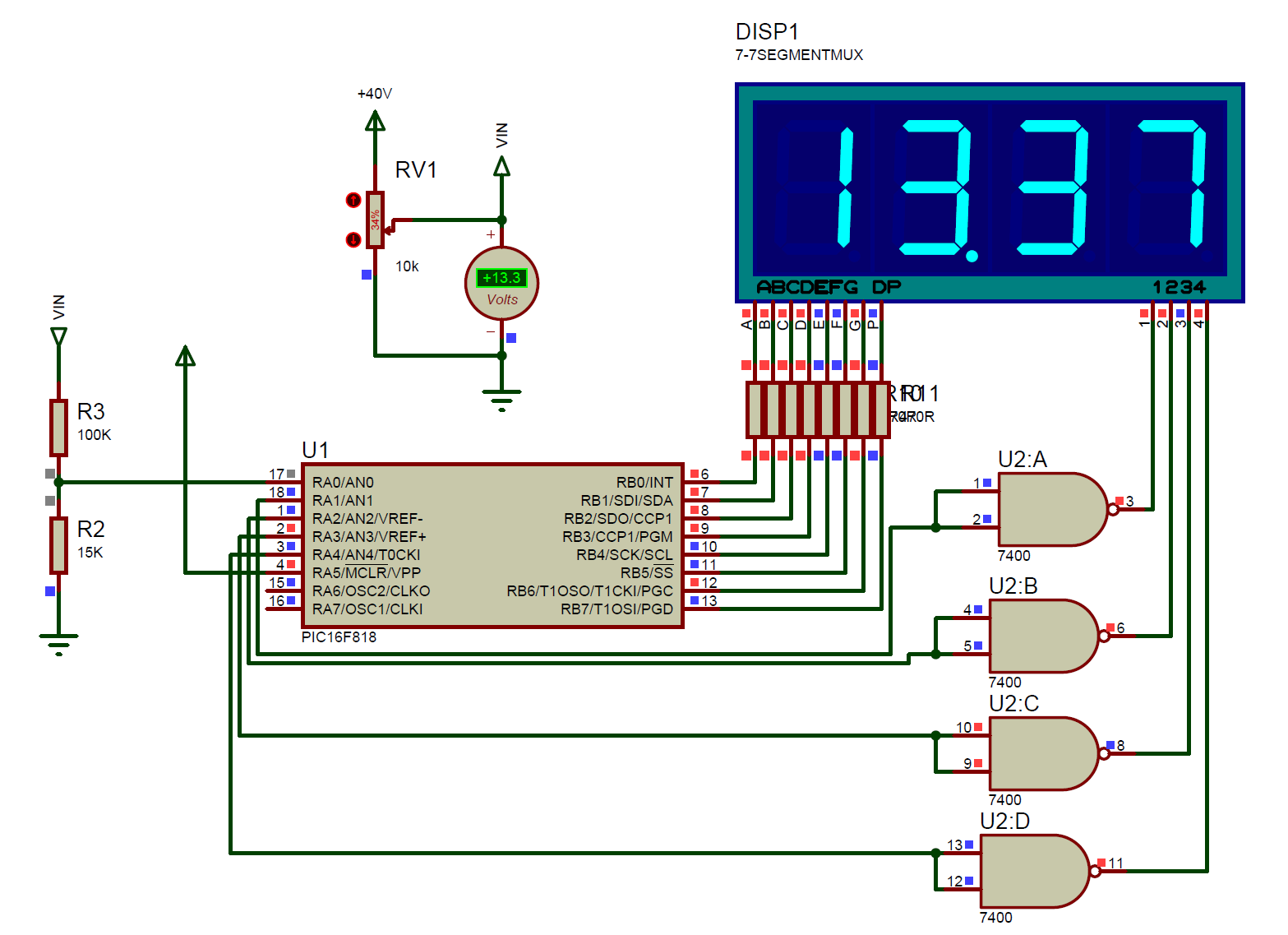
Digital Volt Meter (DVM) could be built from scratch using any ADC IC such as ICL7107 or ICL7135. However those IC have a large pin counts requiring us more time to wire.

Using a microcontroller we can reduce the number of pin count for the display. A common way is using multiplexed display.

In this project I use PIC16F818 with a 10-bit built-in ADC to read analog voltage range from 0 to +40V DC.

ADC work only with +5V. So I use the voltage divider rule to reduce the scale of input voltage. As show in the schematic below, the resistors R3 and R2 are use for voltage divider. From voltage divider rule I get the scale factor of 0.13.

dvm
A schematic capture during simulation

Download this source from GitHub:

https://github.com/BongPeav/CCS-PICC/raw/master/16F818_timer0_ADC_DVM_0_35V.rar

CCS PICC source code for this example:

// PIC16F818 DVM

#include <16f818.h>
#DEVICE ADC=10
#fuses INTRC_IO,NOWDT,NOLVP,NOPUT,NOBROWNOUT
#use delay(clock=4M)

#define LED_DELAY delay_ms(5)

unsigned int16 reader;
unsigned int8 counter;
unsigned int8 number[10]={0x3F,0x06,0x5B,0x4F,0x66,0x6D,0x7D,0x07,0x7F,0x6F};  

float voltage;

#int_timer0
void timer0isr()
{  
  counter++;
}

///////////////////////////////////
void displaydata(float raw){
   unsigned int16 dig4,dig3,dig2,dig1,data,temp1,temp2;
   float mydat;
   mydat=raw*100;
   data=mydat;
   dig4=data/1000;
   temp1=data%1000;
   dig3=temp1/100;
   temp2=data%100;
   dig2=temp2/10;
   dig1=data%10; 
  //////////////////////////////////////////
   output_B(number[dig4]);
   output_high(PIN_A1);
   LED_Delay;
   output_low(PIN_A1);
   ///////////////////////
   output_B(number[dig3]|0x80);
   output_high(PIN_A2);
   LED_DELAY;
   output_low(PIN_A2);
   ////////////////////////////////
   output_B(number[dig2]);
   output_high(PIN_A3);
   LED_DELAY;
   output_low(PIN_A3);
   ///////////////////////////
   output_B(number[dig1]);
   output_high(PIN_A4);
   LED_DELAY;
   output_low(PIN_A4);
}

void main()
{  
   SET_TRIS_B(0x00);
   SET_TRIS_A(0x01);
    SETUP_ADC(ADC_CLOCK_DIV_2);
   SETUP_ADC_PORTS(ALL_ANALOG);
   SET_ADC_CHANNEL(0);
   DELAY_US(30);
   SETUP_TIMER_0(RTCC_DIV_256);
   ENABLE_INTERRUPTS(GLOBAL);
   ENABLE_INTERRUPTS(INT_TIMER0);
   CLEAR_INTERRUPT(INT_TIMER0); 
   while(TRUE)
   {  
      //TODO: User Code    
   //  if(counter==5){
   //  counter=0;    
      reader=read_adc();
      while(!adc_done());  
      voltage=(reader*(5.0/1024))/0.130;
  //    }
      displaydata(voltage);  
   }

}

Any suggestion relates to this post could be sent to the author using the contact form below.

8051 Hello World using AT89C51 in Proteus 8 and Keil

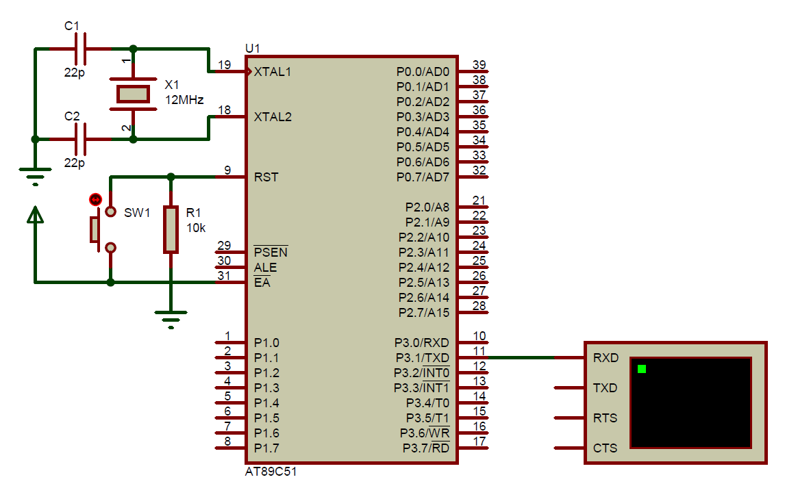
In this program I am writing a C code in KEIL for 8051 printing a “Hello World” message on serial port terminal. The baud rate is 2400.

C Code:

#include <reg51.h>
#include <stdio.h>

void main(void)
 { 
 SCON=0x52; // SET SERIAL PORT TO MODE 1
 TMOD=0x20; // TIMER1 MODE 2
 TH1=-13; // RELOAD COUNTER FOR 2400 BAUD RATE
 TR1=1; // START TIMER1
 // Write your code here
 while (1)
 printf("Hello World\n");
 }

Schematic:

Untitled
The CPU is AT89C51 from Atmel (Microchip) running from crystal at 12MHz.

source:

https://github.com/BongPeav/8051/raw/master/AT89C51_HelloWorld_Proteus_8.rar

Video:

Playing with LEDs on AT89S52 8051 Device

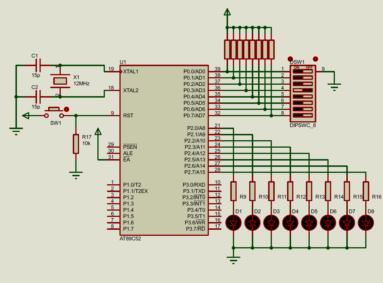
LED chasing is funny. We can chase LED on a simple counter such as CD4017 but it’s limited. AT89S52 is a simple microcontroller at ATMEL (now Microchip) with Intel 8051 architecture. The programming is popular KEIL uVision C51 compiler. I use embedded C for 8051.

The program I wrote function may LED chasing mode such shift righ/left and flow right/left. Those modes are selected using a DIP switch. If it’s not in this mode it will blink all LEDs.

1
In this picture I use AT89C52 instead of AT89S52. P0 is an open-drain port so I add external pullup resistors to it high.


Download this example source:

https://github.com/BongPeav/8051/raw/master/ShiftLED.rar

Keil C  source code:


/* Demo Program on 8051 Basic Test and ISP BOARD
The program to select four mode of LEDs running.
AUTHOR: ENG BUNTHA
*/

#include <REG52.h>

#define rate 10

char FLED;
unsigned char SLED;
void Lshift();
void Rshift();
void Lflow();
void Rflow();
void Pblink();
void mode();

void delay(int val);

void main(){
	P2=0x00;
	P0=0xFF;
	FLED=0x80;
	SLED=0x10;
	while(1)	mode();
}

void delay(int val){
	int i,j;
	for(i=0;i<val;i++)
		for(j=0;j<1000;j++);
}

void Rflow(){
	int k;
	for(k=0;k<8;k++){
		P2=FLED;
		delay(rate);
		FLED>>=1;
	}
	FLED=0x80;
	P2=0x00;
	delay(rate);
}


void Lflow(){
	char LED[8]={0x01,0x03,0x07,0x0F,0x1F,0x3F,0x7F,0xFF};
	int k;
	for(k=0;k<8;k++){
		P2=LED[k];
		delay(rate);
	}
	P2=0x00;
	delay(rate);
}

void Rshift(){
	P2=SLED;
	delay(rate);
	SLED>>=1;
	if(SLED==0x00)	SLED=0x80;
}

void Lshift(){
	P2=SLED;
	delay(rate);
	SLED<<=1;
	if(SLED==0x00) SLED=0x01;
}

void Pblink(){
	P2=0x00;
	delay(rate);
	P2=0xFF;
	delay(rate);
}

void mode(){
	unsigned char sel;
	sel=P0;
	switch(sel){
		case 0x01:	Lflow();
								break;
		case 0x02:  Rflow();
								break;
		case 0x04:  Lshift();
								break;
		case 0x08:  Rshift();
								break;
		default  :  Pblink();
								break;
	}
}